Locating and interpreting the 1997 Ford F-150 fuse box diagram is essential for troubleshooting electrical issues. Follow this guide to understand it efficiently.
Locating the Fuse Boxes
Two primary locations exist:
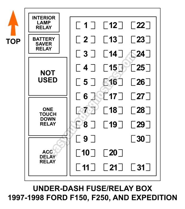
- Interior (Cab): Situated below the dashboard, on the driver's side near the parking brake. Access requires pulling down on the panel.
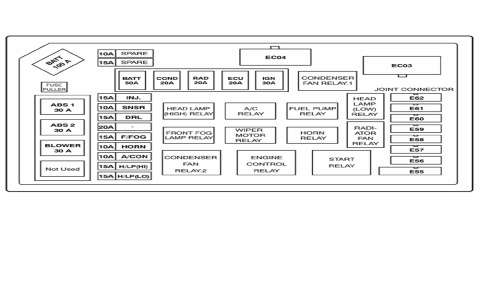
- Engine Compartment: Found on the driver's side near the firewall. Often labeled "Power Distribution Box" and contains high-amperage fuses and relays.
Understanding the Fuse Box Diagram
The diagram maps every fuse slot. Key components include:
- Fuse Number: A unique identifier for each fuse slot (e.g., Fuse 1, Fuse 10). Always match the number on the fuse itself to the diagram.
- Fuse Rating (Amperage): Indicated numerically (e.g., 5A, 10A, 20A, 30A). Never replace a fuse with a higher amperage rating.
- Fuse Type: Primarily standard ATO/ATC blade fuses for cab circuits and larger Maxi fuses for the engine compartment box.
- Protected Component/Circuit: Lists the specific electrical component or system protected by that fuse (e.g., "Brake Lights," "Horn," "PCM," "Blower Motor").
Interpreting Symbols & Layout
- Conventional Diagrams: Often use simplified representations resembling the physical fuse box layout. Fuse numbers are positioned as they appear.
- Chart Format: May list fuse numbers alongside corresponding amperage ratings and the circuit description.
- Relays: Larger squares usually grouped separately; identified by relay numbers (e.g., R1, R2) and the circuit they control (e.g., Fuel Pump Relay, Starter Relay). Refer to the diagram legend.
- Legend/Key: Explains any abbreviations used for circuits (e.g., PCM = Powertrain Control Module, T/SIG = Turn Signal).
Practical Steps to Read the Diagram
- Identify the Box: Determine whether the diagram applies to the interior cab box or the engine compartment power distribution box.
- Locate the Fuse Number: Find the number of the fuse you are checking on the diagram.
- Verify Amperage & Circuit: Cross-reference the diagram entry to see the correct amperage rating and which electrical circuit it protects.
- Identify Relays (If Needed): Find the relay number and its associated circuit.
Safety & Replacement Tips
- Disconnect Battery: Always disconnect the negative battery cable before removing or replacing fuses or relays.
- Inspect the Fuse: Visually check the metal element inside the transparent plastic housing. A broken filament indicates a blown fuse.
- Exact Replacement: Use a fuse of the precise amperage rating and physical size (Mini, Standard, Maxi).
- Fuse Puller Tool: Utilize the fuse puller tool typically clipped inside the cab fuse box lid.
- Investigate Root Cause: A blown fuse often signals an underlying problem. Repeatedly blowing the same fuse indicates a short circuit or malfunction that needs diagnosis.