Use a multimeter safely and accurately to diagnose brake light switch wiring with this procedure:
Tools Required
- Digital Multimeter (DMM)
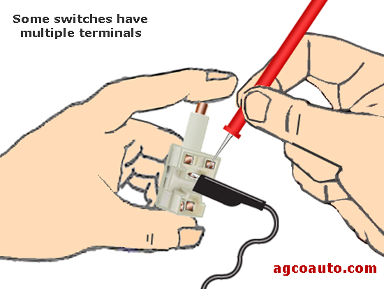
- Vehicle Wiring Diagram (Identify switch terminal functions)
Safety Preparation
Park vehicle on level ground, set parking brake, and disconnect negative battery terminal.
Locate the brake light switch, typically mounted near the brake pedal arm. Access requires kneeling safely.
Confirming Power Supply (Voltage Test)
- Reconnect battery or ensure appropriate ignition position (often "ON" or "RUN" per diagram).
- Set DMM to measure DC Volts (20V range).
- Identify the switch power input wire (usually fused, "hot" with ignition on).
- Connect DMM black probe to chassis ground.
- Touch DMM red probe to power input terminal/connector pin. Verify 12V presence. If absent:
- Check related fuse.
- Trace for wiring faults upstream.
Testing Switch Operation (Continuity/Voltage Tests)
Disconnect the switch electrical connector if possible.
Method A: Continuity Test (Switch Unplugged)
- Set DMM to continuity or Ohms (Ω) mode.
- Identify switch terminals (NO Normally Open & NC Normally Closed, common, or refer to diagram).
- Brake Pedal Released:
- Continuity should exist between NC terminals (if applicable).
- NO terminals should read Open Circuit (OL).
- Brake Pedal Pressed:
- Continuity should exist between NO terminals.
- NC terminals should read Open Circuit (OL).
Method B: Voltage Output Test (Switch Connected)
- Reconnect switch connector if disconnected.
- Set DMM to DC Volts (20V range).
- Connect DMM black probe to chassis ground.
- Identify switch output wire/terminal (to brake lights).
- Brake Pedal Released: Probe output wire. Should read near 0V.
- Brake Pedal Pressed: Probe output wire. Should read near 12V.
Ground Verification
Continuity Test:
- Set DMM to continuity or Ohms (Ω) mode.
- Identify brake light ground wire/path from diagram.
- Disconnect brake light connector(s).
- Place one DMM probe on bulb socket ground terminal/pin.
- Place other probe on chassis ground point. Continuity must exist (0-1 Ω). High resistance indicates a bad ground.
Interpretation
- Missing Input Power: Fault lies upstream (fuse, wiring, ignition feed).
- Switch Continuity Tests Fail: Replace brake light switch.
- Correct Switching Voltage Present, Lights Inoperative: Test circuit output wire, bulb sockets, bulbs, and ground paths.