Understanding GM 4L60E transmission wiring diagrams requires systematic analysis. Follow these steps:
1. Gather Necessary Documentation
Obtain the specific wiring diagram for your vehicle's model year and engine. Diagrams are typically found in Factory Service Manuals (FSM) or reputable aftermarket repair databases. Ensure it clearly shows the transmission control section and Powertrain Control Module (PCM) connections.
2. Identify Key Diagram Components
- Connector Views: Locate diagrams showing the transmission connector(s) (often a large, multi-pin connector near the transmission case) and the PCM connector pinouts.
- Wire Colors & Numbers: Note wire color abbreviations (e.g., BLK=Black, PPL=Purple, YEL=Yellow) and circuit numbers alongside each line.
- Component Symbols: Recognize standard symbols: squares/rectangles (connectors), circles (splices), triangles (ground points), component-specific symbols (solenoids, switches).
- Abbreviations: Decode common labels: TCC (Torque Converter Clutch), PWM (Pressure Control Solenoid), PCS (Pressure Control Solenoid), VSS (Vehicle Speed Sensor), ISS (Input Speed Sensor), OD (Overdrive), 1-2, 2-3, 3-4 (Shift Solenoids).
3. Trace Power, Ground, and Signal Circuits
- Power (B+): Trace wires from the battery (often fuse-protected) to components like solenoids or sensors. Common feed circuits might be labeled "IGN" or "BATT".
- Ground (GND): Identify wires terminating at ground symbols (G100, G101, etc.). Verify clean chassis/engine block grounds are critical for proper operation.
- Control Signals: Focus on circuits connecting transmission components (solenoids, sensors) directly to specific PCM pins. The PCM typically supplies switched ground paths for solenoids and interprets input signals (sensors, switches).
4. Analyze Specific Transmission Circuits
Methodically examine these core system circuits:
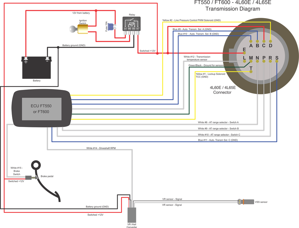
- Shift Solenoids (SS A/1-2 & SS B/2-3): Identify the wire color/number from each solenoid to the PCM. Diagrams show PCM providing the ground path for activation.
- Torque Converter Clutch (TCC) Solenoid/PWM Solenoid: Locate the control circuit to the PCM. PWM solenoids often have a dedicated power feed and a PWM ground control from the PCM.
- Pressure Switch Manifold (PSM): Identify the individual switch circuits (e.g., TCC, 3-2, 4-3, Low). These are typically switches providing either a ground signal or an open circuit when activated. Trace each switch's wire to the PCM input pin.
- Speed Sensors (VSS & ISS): Find the sensor's power, ground, and signal output wires. The signal wire connects directly to designated PCM pins for calculation. Signal types vary (AC sine wave for inductive sensors, digital square wave for hall-effect).
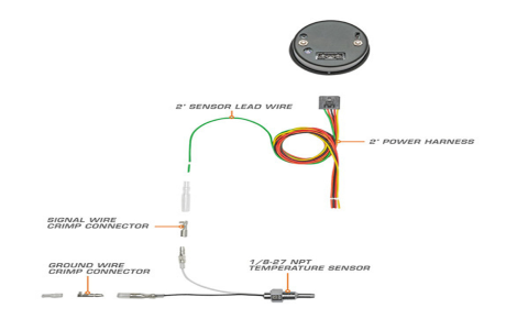
- Transmission Fluid Temperature (TFT) Sensor: Identify the reference voltage (usually 5V) from PCM, the sensor ground (low reference), and the signal return wire to the PCM's analog input.
- Range Selector (PRNDL) Switch: Trace the multiple position signal wires from the transmission selector to the PCM/Instrument Cluster. Each gear position typically uses a unique wire sending specific voltage signals.
5. Verify Continuity and Isolation
Use a digital multimeter (DMM) or wiring diagram to check:
- Continuity: Ensure wires connect from point-to-point without breaks (e.g., sensor signal terminal to PCM pin terminal).
- Resistance: Measure solenoid/component resistance against specs.
- Shorts to Ground/Power: Verify no circuit wire has unintended contact with chassis ground or battery positive.
- Signal Verification: Use appropriate tools (scanner for solenoid commands, oscilloscope/DMM for sensor outputs) to confirm signals match diagram and component operation.
Critical Practice: Always cross-reference the wire colors and circuit numbers shown on the diagram against your actual vehicle harness. Compare connector cavity numbers meticulously. Pinout variations exist between model years.