P1023 indicates a fault within the Throttle Actuator Control (TAC) Module's low voltage circuit (Bank 1). This requires immediate attention as it affects throttle response and engine performance.
Necessary Preparations
Gather these items:
- OBD-II scanner
- Digital Multimeter (DMM)
- Basic hand tools (screwdrivers, wrenches)
- Vehicle-specific service manual
- Electrical contact cleaner
- Dielectric grease
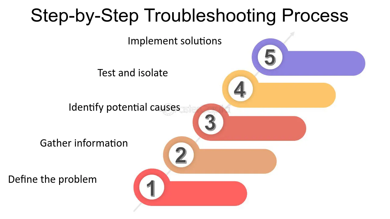
Step-by-Step Troubleshooting
1. Verify Code & Battery Voltage:

Re-scan with your OBD-II tool to confirm P1023. Check the vehicle battery voltage; it must read at least 12.6V when engine-off. Low battery voltage can cause erroneous faults.
2. Inspect Visual Connections:
Locate the TAC module (often near the throttle body) and the main Engine Control Module (ECM). Visually examine:
- Wiring harnesses for physical damage, chafing, or burns
- TAC module and ECM electrical connectors for corrosion, bent pins, or loose fit
- Ground points connected to the TAC system (cleanliness and tightness are critical)
Disconnect plugs and clean terminals using contact cleaner; apply dielectric grease upon reconnection.

3. Perform Voltage Checks with DMM:
Referencing the service manual wiring diagrams:
- Identify the TAC module's specific low-reference circuit.
- With ignition ON (engine OFF), measure voltage: Connect DMM ground probe securely to chassis ground. Backprobe the low-reference circuit wire at the TAC connector.
- A healthy circuit typically shows less than 0.5V. Voltages above 0.5V signify excessive resistance or a short.
- Similarly, check the power and ground circuits to the TAC module per specifications.
4. Continuity & Resistance Checks:
Power off and disconnect TAC/ECM! Use DMM resistance/continuity mode:

- Check continuity from the TAC low-reference pin to the designated ECM pin. No continuity confirms an open circuit.
- Measure resistance on the low-reference circuit between TAC and ECM. Resistance should be very low (< 5 Ohms). Higher resistance indicates corrosion or damaged wires.
- Verify ground circuit resistance to chassis (< 5 Ohms).
5. Check Related Sensors & Throttle Body:
Key inputs: Inspect the Throttle Position Sensor (TPS) and Accelerator Pedal Position (APP) sensor connectors/wiring. A faulty sensor can corrupt TAC communication. Manually check the throttle body for binding or excessive carbon buildup hindering movement.
Common Solutions
Based on findings:
- Repair Wiring: Fix damaged wires, corroded terminals, or loose ground connections found during testing.
- Replace Sensor(s): If APP or TPS shows faults or inconsistent readings, replacement is likely needed.
- Replace Throttle Body/TAC Module: If wiring/sensors are verified good but voltage/resistance faults persist, or mechanical throttle issues exist, replacement is necessary. Note: TAC/Throttle Body replacements often require a throttle relearn procedure (follow specific vehicle instructions).
- Replace ECM: Rare, but becomes probable if all low-reference circuit checks prove integrity and TAC module tests good.
Final Step: Clear all DTCs with your scanner. Perform a test drive under varied conditions to verify the P1023 code does not return.

