Proper installation of spark plug wires on a Chevy 350 engine is critical to prevent misfires, rough idling, and reduced efficiency. This guide ensures you avoid firing issues with clear, easy-to-follow steps.
Core Firing Order and Setup
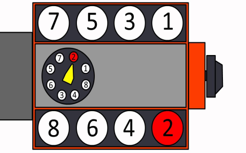
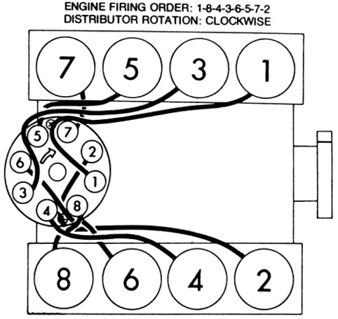
The Chevy 350 small-block V8 has a firing order of 1-8-4-3-6-5-7-2. Always reference the distributor cap's numbered terminals, typically located at the front of the engine.
- Stand facing the engine with the radiator at your front: cylinder 1 is front driver's side, cylinder 2 front passenger's side, cylinder 3 rear driver's side, cylinder 4 rear passenger's side, cylinder 5 front driver's side opposite bank, cylinder 6 front passenger's side opposite bank, cylinder 7 rear driver's side opposite bank, and cylinder 8 rear passenger's side opposite bank.
- Route wires from the ignition coil to the distributor cap terminal marked for cylinder 1.
- Then connect from distributor terminal 1 to spark plug cylinder 1.
- Proceed sequentially: terminal 8 to cylinder 8, terminal 4 to cylinder 4, terminal 3 to cylinder 3, terminal 6 to cylinder 6, terminal 5 to cylinder 5, terminal 7 to cylinder 7, and terminal 2 to cylinder 2.
Verify all wires are of correct length to prevent stretching or contact with hot components.
Key Steps for Avoidance
Prevent common firing issues with these pro tips:
- Crossed wires: Double-check routing using simple pencil-and-paper diagrams, sketching the firing order and cylinder positions for visual confirmation.
- Insulation and wear: Inspect wires annually for cracks or burns; replace if resistance exceeds 10k ohms per foot.
- Interference: Secure wires with separators to avoid arcing against engine blocks or headers.
Test the setup by starting the engine and listening for smooth operation; any miss indicates reevaluation.
Using Simple Diagrams
Create easy diagrams: draw the distributor cap with labeled terminals and map connections to each cylinder. For a standard setup, cylinders form a V with 1-3-5-7 on the driver's side bank and 2-4-6-8 on the passenger's side.
Consult manufacturer schematics for specific variations, always prioritizing safety by disconnecting the battery before work.