Electrical issues in your 1997 Ford F150 often originate at the fuse boxes. Locating and correctly interpreting the diagram is crucial for efficient diagnosis.
Locating Fuse Boxes
Your F150 has two primary panels:
- Interior Fuse Panel: Positioned below the steering column near the brake pedal. Remove the rectangular plastic cover by pulling it straight towards the seat.
- Power Distribution Box (PDB): Located under the hood, driver's side, near the brake master cylinder/ABS unit (if equipped). It contains high-amperage fuses and relays. Lift the cover vertically.
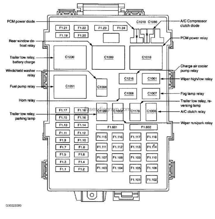
Using the Diagrams
- Matching Physical Layout: Diagrams depict fuse/relay positions exactly as they appear in the panel. Find the corresponding slot.
- Deciphering Labels: Each slot has a number/letter code (e.g., F1.14, F2.3). Match this code to the diagram. Components are listed by circuit name and fuse amperage (e.g., "Stop Lamp 15A").
Troubleshooting Common Circuits
Focus on these frequent problem points first:
- Interior Panel F15 (15A): Stop Lamps (Brake Lights). Failures here cause no brake lights or shift interlock issues.
- Interior Panel F1 (30A Circuit Breaker): Power Windows. Stuck windows often start here.
- Interior Panel F2.8 (15A) & F2.10 (10A): Instrument Cluster/Gauges. Gauges failing? Check these.
- Interior Panel F13 (15A): Turn Signals/Hazard Flashers. No turn signals? Verify this fuse.
- Power Distribution Box Fuse 4 (40A): Ignition Switch Feed (Start/Run power). Engine crank/no-start or no accessories? Suspect this.
- Power Distribution Box Fuse 6 (30A): PCM Power (Engine Computer). Engine stalls or won't start? Critical fuse.
- Power Distribution Box Fuse 9 (30A): Fuel Pump Driver Module (or direct to pump). No fuel pump prime? Check immediately.
- Power Distribution Box Relays: Especially Relay 1 (Fuel Pump) and Relay 4 (Main). Audible click when key turned on? If not, suspect relay failure.
Diagnostic Procedure
- Identify Symptom: Note exactly which system fails (e.g., "Right headlight low beam," "Radio has no power").
- Consult Diagram: Locate the fuse(s) responsible for that specific circuit.
- Visual & Physical Inspection:
- Inspect suspect fuses. Look for broken filament (glass fuses) or melted/blown element (blade fuses).
- Check fuse terminals in the panel for corrosion or burning.
- Use a test light or multimeter. Test for power on both sides of the fuse with key/switch on. No power on one side = blown fuse.
- Swap identical amp relays (like HVAC blower for fuel pump) as a test.
- Replace Faulty Component: Use a fuse of the exact same amperage rating. Never oversize. Ensure relays snap fully into sockets.
Critical Safety Step:
Always disconnect the negative battery terminal before accessing or working on fuse panels to prevent shorts. If a new fuse blows immediately, a serious short circuit exists downstream – professional diagnosis is required.