Understanding the 4-Pin Brake Light Switch
The 4-pin brake light switch is crucial for activating brake lights in vehicles. It typically has pins for power input, output to lights, ground, and a redundant circuit. A failure here often causes no illumination or erratic behavior.
Common Causes of Brake Light Failure
- Faulty switch mechanism due to wear or contamination
- Damaged wiring or poor connections at pins
- Blown fuse affecting the switch circuit
- Ground issues or corroded terminals
Troubleshooting with the 4-Pin Switch Diagram
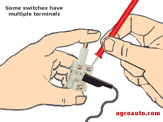
Refer to the vehicle's schematic to identify pin functions. Typical pinout is: Pin 1 (power from fuse), Pin 2 (output to lights), Pin 3 (ground), and Pin 4 (auxiliary circuit). Test connectivity step-by-step.
Step-by-Step Diagnostic Guide
- Check fuse continuity; replace if blown.
- Use a multimeter to test power at Pin 1 with brake pedal depressed.
- Measure voltage between Pin 2 and ground; no reading indicates switch failure.
- Verify ground at Pin 3 for continuity to chassis.
- Inspect wiring for shorts or breaks along signal paths.
Repair Solutions
Replace defective switches immediately. Ensure pins align correctly during installation. Repair or solder damaged wires using insulated connectors. Clean corroded terminals with electrical contact cleaner.
Safety Tips
Disconnect battery before repairs to prevent shorts. Always test lights after fixes to confirm functionality.