Accurate voltage testing of crank position sensors requires understanding their wiring and operating principles. Always disconnect the battery negative terminal before handling connectors. Typical sensor types include Hall Effect (3-wire) and Magnetic Reluctance (2-wire).
Sensor Wiring Identification
Locate the sensor connector. Identify wires using wiring diagrams specific to your vehicle make/model/year. General configurations:
- Hall Effect Sensor (3 wires):
- Reference Voltage (Vref): Typically 5V or 12V (supply from ECU)
- Signal Output: Carries digital square wave signal
- Ground (GND): Sensor return path to ECU/battery negative
- Magnetic Reluctance Sensor (2 wires):
- Signal Output: Generates AC voltage sine wave
- Sensor Ground/Shield: Usually connected to engine block
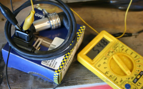
Testing Voltage with Multimeter
Preparation:

- Set multimeter to DC Voltage for Hall sensors, AC Voltage for Magnetic sensors
- Reconnect battery negative. Leave sensor connected. Back-probe terminals using thin pins at the connector rear.
Hall Effect Sensor Test:
- Identify Vref wire. Measure between Vref and battery ground: Should read 5V or 12V ±0.5V with ignition ON (engine OFF).
- Measure between Signal and Ground: Should read ≈50% of Vref (e.g., 2.5V for 5V ref) with ignition ON, engine OFF.
- Critical Test: Measure Signal to Ground while cranking engine. Fluctuating DC voltage (0V-Vref) confirms operation. A flatline indicates failure.
Magnetic Reluctance Sensor Test:
- Set multimeter to AC Voltage.
- Back-probe signal wire and ground wire.
- Crank engine: Meter should display >100mV AC (often 0.5V-2V+ AC). No AC voltage indicates faulty sensor or wiring.
Interpreting Results
| Symptom | Likely Cause |
|---|---|
| No Vref | Open circuit in supply wire, blown ECU fuse |
| Vref too low | Short to ground in supply/signal wire |
| Signal = Vref constant | Signal wire shorted to Vref |
| Signal = 0V constant | Signal wire shorted to ground or open circuit |
| Weak/no AC voltage | Failed sensor, incorrect gap, damaged reluctor wheel |
Cautions:
- Never probe wires by piercing insulation on running vehicles.
- Use manufacturer gap specifications if sensor removal is required.
- Steady DC voltage at Hall sensor signal during cranking = failure. Voltage must fluctuate.