The correct firing order for the 2005 Ford Explorer equipped with the 4.0L V6 engine is 1-4-2-5-3-6. This order must be strictly followed to ensure proper engine operation.
Locating the Firing Order Diagram
Find the official diagram using these primary sources:
- Underhood Emissions Label: Check the Vehicle Emission Control Information (VECI) decal, typically located on the underside of the hood or near the radiator support. This label often includes a firing order diagram among other engine specifications.
- Repair Manual: Consult the vehicle-specific section of a Ford factory service manual or reputable aftermarket manuals (e.g., Haynes, Chilton).
Identifying Cylinder Banks
Standing at the front of the vehicle (facing the windshield):
- Front Bank (Bank 1): The passenger side cylinder bank (right side). Contains cylinders 1, 2, 3.
- Rear Bank (Bank 2): The driver side cylinder bank (left side). Contains cylinders 4, 5, 6.
Cylinder Numbering
- Cylinder #1: Front-most cylinder on the passenger side bank (Bank 1).
- Cylinder #2: Middle cylinder on the passenger side bank (Bank 1).
- Cylinder #3: Rear-most cylinder on the passenger side bank (Bank 1).
- Cylinder #4: Front-most cylinder on the driver side bank (Bank 2).
- Cylinder #5: Middle cylinder on the driver side bank (Bank 2).
- Cylinder #6: Rear-most cylinder on the driver side bank (Bank 2).
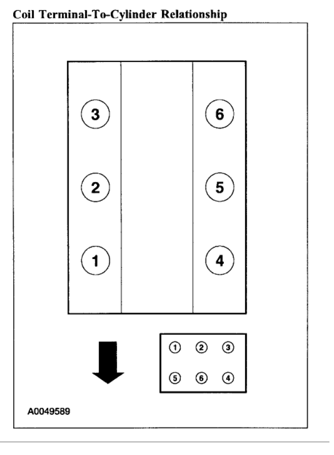
Component Identification & Routing
Coil Pack Identification: The 4.0L engine uses a distributorless ignition system (DIS) with a coil pack typically mounted near the center top of the engine. The coil pack has terminals numbered corresponding to the firing order sequence or cylinder pairs (usually: Cyl 1-6, Cyl 2-5, Cyl 3-4 share coils). Use the diagram source to confirm terminal numbering.
Ignition Wire Routing:
- Confirm the engine is cold before starting.
- Remove one spark plug wire at a time from both the coil pack terminal and the spark plug. Clean it and label it clearly with its cylinder number using masking tape.
- Consult the verified firing order diagram (1-4-2-5-3-6) and the coil pack terminal numbering.
- Starting with Cylinder #1 (passenger side front), route its wire to its designated coil pack terminal (confirmed by diagram).
- Follow the firing order sequence 1-4-2-5-3-6:
- Cylinder #1 wire
- Cylinder #4 wire (driver side front)
- Cylinder #2 wire (passenger side middle)
- Cylinder #5 wire (driver side middle)
- Cylinder #3 wire (passenger side rear)
- Cylinder #6 wire (driver side rear)
- Ensure wires are securely snapped onto both the spark plug nipples and the coil pack terminals. Route wires neatly through factory separators/clips to prevent cross-fire or chafing.
Critical: Always use the verified diagram from one of the listed sources. Do not guess the order or cylinder locations, as an incorrect firing order will cause severe misfires and potential engine damage.