Understanding the Vacuum System
The vacuum system in the 2001 Ford F150 4.6L engine manages critical functions like EGR operation, fuel vapor recapture, and HVAC controls. Issues such as rough idling, poor fuel economy, or check engine lights often stem from vacuum leaks or degraded hoses.
Accessing the Vacuum Hose Diagram
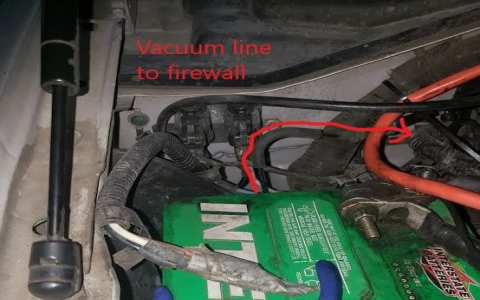
Locate the vacuum hose diagram inside the engine compartment; it is frequently attached to the hood liner or firewall label. If absent, consult the owner's manual or service specifications for a standard layout.
- Steps: Open the hood, inspect visible areas for the diagram label.
- Tools Required: Flashlight for improved visibility in confined spaces.
- Safety Precautions: Wear gloves to avoid cuts and disconnect the battery to prevent electrical hazards.
Interpreting the Vacuum Diagram
The diagram maps all hoses, valves, and components using color codes or alphanumeric labels for each circuit. Focus on these key sections:
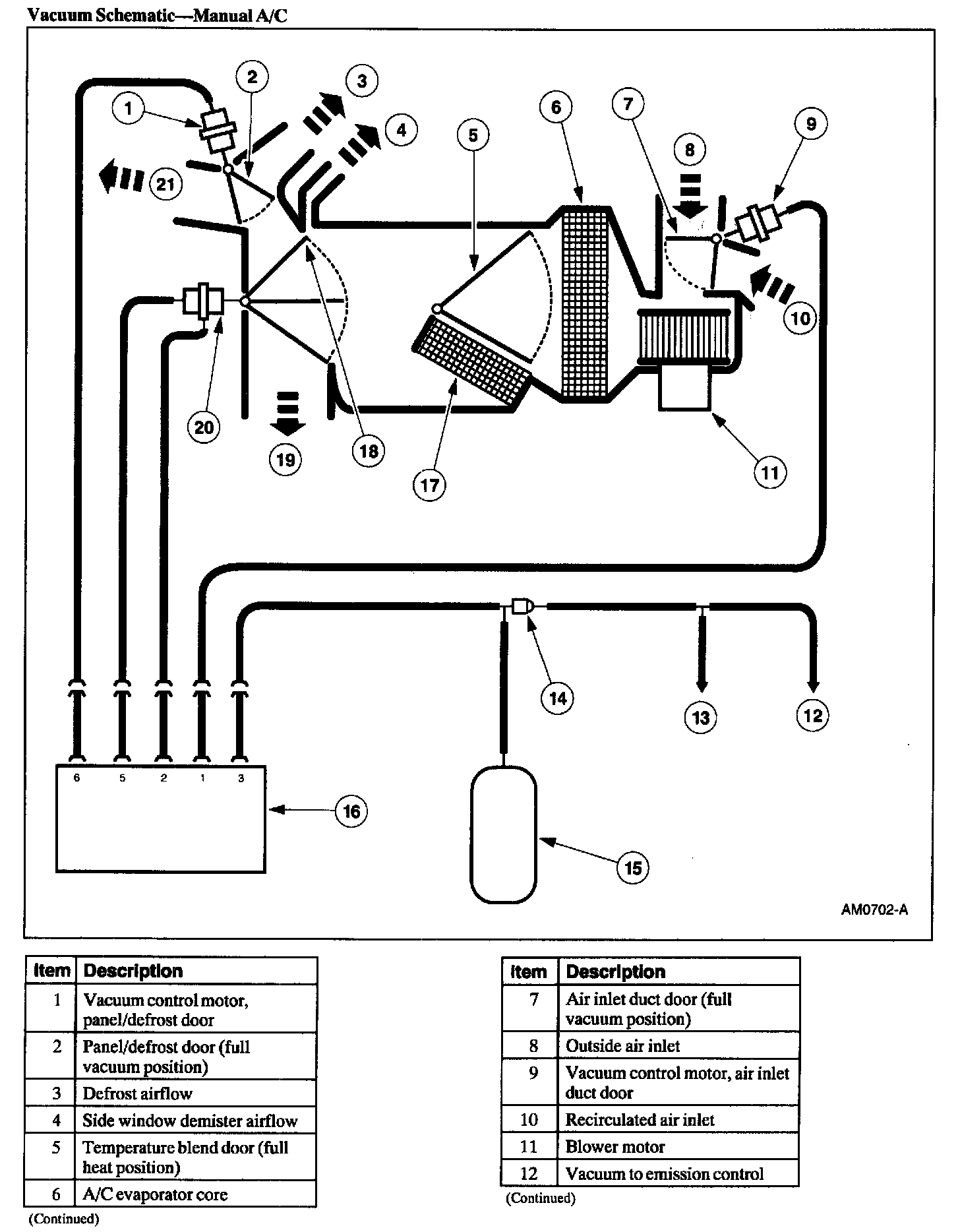
- Hose Routing: Traces connections from the intake manifold to devices like the brake booster or PCV valve.
- Component Symbols: Identifies check valves, solenoids, and sensors; cross-reference with engine specifics.
- Common Trouble Spots: Highlight areas prone to failure, such as rubber junctions under high heat or vibration points.
Accessing Vacuum Hoses for Inspection
Remove necessary components to reach hoses without causing damage. Start by disconnecting the air intake assembly and upper engine covers.
- Sequence:
- Detach negative battery cable.
- Remove air cleaner housing screws and lift out.
- Gently pry off any plastic covers to expose hoses along the firewall and manifold.
- Challenge Avoidance: Avoid kinking or straining old hoses; document connections before disassembly.
Fixing Vacuum Hose Issues
Diagnose leaks using a vacuum gauge or smoke tester. Repair common problems like cracks or loose fittings promptly to restore system integrity.
- Leak Testing: Apply soapy water to hoses; bubbles indicate leaks under vacuum pressure.
- Replacement Procedure: Cut hoses to size using a sharp knife, use OEM-grade rubber replacements for compatibility.
- Securing Connections: Reattach with hose clamps, ensuring proper tension to prevent slippage; test with a scan tool for error codes.
Conclusion and Best Practices
Regular inspection every 50,000 miles prevents major failures. Always verify repairs with a test drive to confirm smooth engine operation.