Reading GMC truck instrument cluster wiring diagrams requires understanding pinouts and color codes. Follow these step-by-step methods for accurate diagnosis.
Prepare for Wiring Diagram Analysis
Gather essential tools like a multimeter and safety gloves. Disconnect the battery before starting to prevent electrical shorts. Always refer to the vehicle-specific diagram, as pinouts vary by model year.
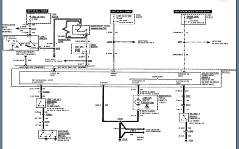
Step 1: Identify Connector Pinouts
Locate the instrument cluster connector in the diagram. Pinouts list each wire's function:
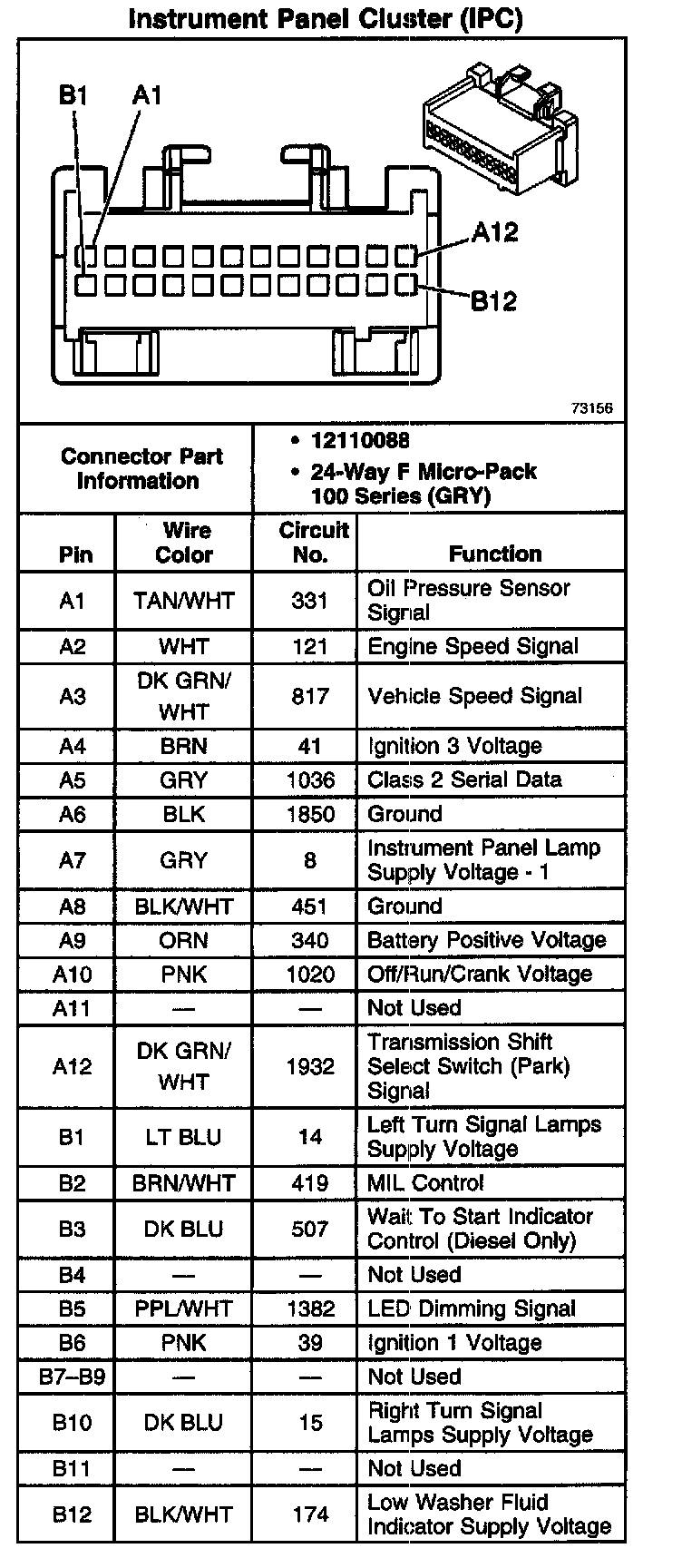
- Pin Numbers: Match numbered pins to connector positions.
- Wire Functions: Common labels include IGN (ignition), BAT (battery), GND (ground), and sensor inputs.
Step 2: Decode Wire Color Coding
Colors indicate circuit types:
- Red or Orange: Typically battery power.
- Black: Ground connections.
- Other Colors: Check legends for sensor signals like speed or fuel.
Step 3: Interpret Diagram Symbols
Understand standard symbols:
- Battery Icon: Shows power sources.
- Ground Symbol: Denotes chassis connections.
- Switches and Sensors: Represented by specific shapes for inputs.
Step 4: Test Connections with a Multimeter
Set the multimeter to continuity mode. Probe each pin per the diagram:
- Verify Power: Test for 12V on IGN and BAT pins.
- Check Grounds: Ensure low resistance to chassis.
Step 5: Trace Circuits for Troubleshooting
Follow wires from cluster to sensors. Focus on inconsistencies like no readings or warnings. Document findings for repairs.
Practice these steps to master wiring diagram interpretation efficiently. Always double-check against vehicle data for accuracy.