The fuse box in your 2004 Nissan Xterra houses critical electrical protection components, with a diagram displaying symbols to identify fuses. Understanding these symbols ensures accurate troubleshooting and prevents damage to your vehicle's systems. Always refer to the fuse box cover diagram or your owner's manual for precise details specific to your make and model.
Locating the Fuse Box Diagram
Your Xterra's fuse box diagram is typically printed on the inner surface of the fuse box cover. If unavailable, consult the owner's manual under the electrical section. Ensure the vehicle is off, keys removed, and battery disconnected before inspecting to avoid electrical hazards.
Key Symbols on the Diagram
The diagram uses standardized symbols to represent fuse details. Common symbols include:
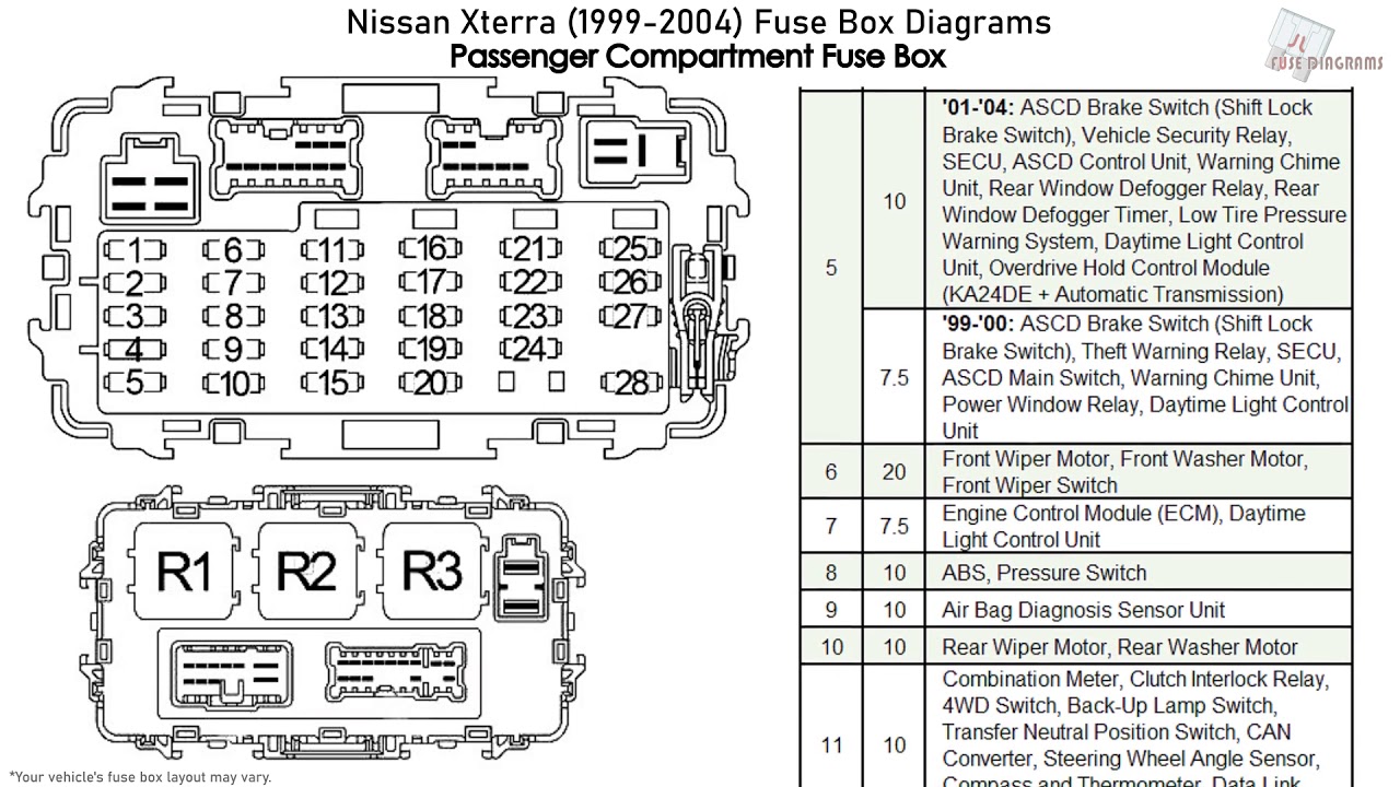
- Fuse Number - A numerical code indicating the specific fuse slot for identification. Example: "F10" refers to fuse position 10.
- Ampere Rating - Symbolized as "A" followed by a number (e.g., "10A"), denoting the current rating; using a higher value fuse risks system damage.
- Component Name - Abbreviated labels describing the protected circuit, like "ENG" for engine control or "RADIO" for audio system.
- Color Coding - Colored blocks or text correlate with fuse ratings; refer to the legend for color-to-ampere mappings.
- Relay Indicators - Symbols like a coil icon point to relay locations, essential for circuits with higher loads.
Interpreting and Using the Diagram
Cross-reference symbols with actual fuses: match the fuse number to the physical slot. If a fuse blows, check the symbol for clues—e.g., a "PWR OUTLET" failure might indicate an accessory overload. Replace only with an exact ampere-rated fuse to maintain safety.
Essential Safety Precautions
Always disconnect the battery negative terminal before accessing the fuse box. Never bypass fuses or use substitutes; incorrect replacements can lead to electrical fires or component failure. Consult a professional if symbols are unclear or issues persist.