This guide provides a step-by-step Chevrolet headlight switch wiring connection procedure. Refer to the terminal view diagram below.
Terminal Functions & Wire Colors (Typical - Confirm Model Specific Diagram)
- Terminal A (Battery Feed/Input):
- Connect constant +12V power source (usually fused, directly from battery or distribution block).
- Often uses a Red wire or Orange wire.
- Terminal B (Parking Lights Output):
- Output to parking lights and instrument panel illumination.
- Commonly Brown wire or Grey wire.
- Terminal C (Dimmer (Instrument Lights) Input):
- Connection for the dash dimmer control potentiometer.
- Typically Gray wire or Tan wire.
- Terminal D (Headlight Switch Ground):
- Connect to a clean chassis or dash metal ground point.
- Usually a Black wire.
- Terminal E (Headlights Output - Low Beam):
- Output feeding low beam headlights (often via relay).
- Frequently Tan wire or Yellow wire.
- Terminal F (Headlights Output - High Beam):
- Output feeding high beam headlights (often via relay).
- Often Light Blue wire or Green wire.
- Terminal G (Daytime Running Lamps (DRL) - If Equipped):
- Output for DRL module/power.
- Wire color varies widely; check diagram (Dark Green common).
Terminal Diagram Layout
Visualize the switch back terminal locations:
A B C
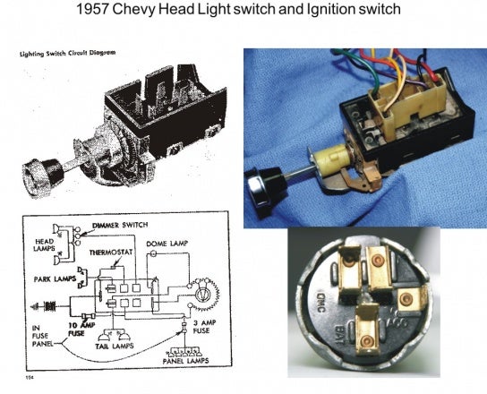
D E F G
(Where A, B, C are the top row; D, E, F, G are the bottom row)
Connection Steps
- Disconnect Battery: Always disconnect the negative battery terminal before wiring.
- Access Switch Socket: Remove the necessary trim/dash panels to access the headlight switch wiring socket/plug.
- Identify Wires: Match existing vehicle harness wires to the terminal functions listed above using a multimeter or wiring diagram.
- Connect Ground: Securely attach the switch's ground wire (Terminal D - Black) to a solid bare metal chassis point.
- Connect Battery Feed: Connect the fused constant +12V power source wire to Terminal A (Red/Orange).
- Connect Outputs:
- Parking Lights: Harness wire to Terminal B (Brown/Grey).
- Dimmer Control: Connect dimmer potentiometer wires per diagram to Terminal C (Gray/Tan).
- Connect Headlight Feeds:
- Low Beam Output: Harness wire to Terminal E (Tan/Yellow).
- High Beam Output: Harness wire to Terminal F (Light Blue/Green).
- Connect DRL (If Equipped): Connect the DRL output wire to Terminal G (e.g., Dark Green) per the vehicle schematic.
- Secure Socket: Reinsert the wiring plug/socket firmly into the switch back.
- Reconnect Battery & Test: Reconnect the battery negative terminal and thoroughly test all lighting functions: parking lights, headlights (low/high beams), instrument dimming, and DRL (if equipped).
Important Notes:
- Model Variations: ALWAYS obtain the specific wiring diagram for your Chevrolet year/model. Terminal locations, functions, and wire colors vary.
- Relay Integration: The switch outputs (Terminals E & F) usually control relays supplying high current to the headlights directly. Check relay wiring if headlights malfunction.
- Circuit Protection: Ensure all circuits have adequate fuse protection per the factory diagram.
- Multimeter Use: Essential for verifying wire functions and power/ground.