Locating the correct wiring diagram for a 2001 Ford F-150 radio requires accessing reliable technical resources. Here's a focused approach:
Core Principles for Locating Wiring Information
- Vehicle Specificity: Ensure any diagram or guide explicitly states compatibility with the 2001 Ford F-150, including the correct trim level if possible (e.g., XL, XLT, Lariat). Different trims and speaker/radio options can affect wiring.
- Authoritative Sources: Prioritize information from Ford factory service manuals, reputable automotive repair databases, or established automotive wiring diagram publishers. Manufacturer documentation holds the highest accuracy.
- Connector Focus: Identify the physical connectors behind the factory radio. The 2001 F-150 typically uses specific harnesses. Knowing the connector shapes and pin counts is crucial for matching a diagram correctly.
Key Wiring Components
Understand the standard functions associated with each wire color in the radio harness:
- Constant 12V (Battery): Typically Yellow. Powers radio memory (presets, time).
- Switched 12V (Ignition/Accessory): Typically Red. Powers the radio on/off with the key.
- Ground: Typically Black. Completes the circuit.
- Illumination: Typically Orange or Orange/White. Dims radio display with headlights.
- Antenna Trigger: Typically Blue. Signals power antenna to extend (if equipped).
- Amplifier Turn-On: Typically Blue/White. Turns on an external factory amplifier (if equipped).
- Speaker Wires: Pairs like White/White-Black (Front Left +/-), Gray/Gray-Black (Front Right +/-), Green/Green-Black (Rear Left +/-), Purple/Purple-Black (Rear Right +/-). Note: Polarity (stripe = negative) is important.
Warning: Wire colors can occasionally vary slightly between harnesses or trim levels. Always verify with a multimeter where possible, especially for power and ground.
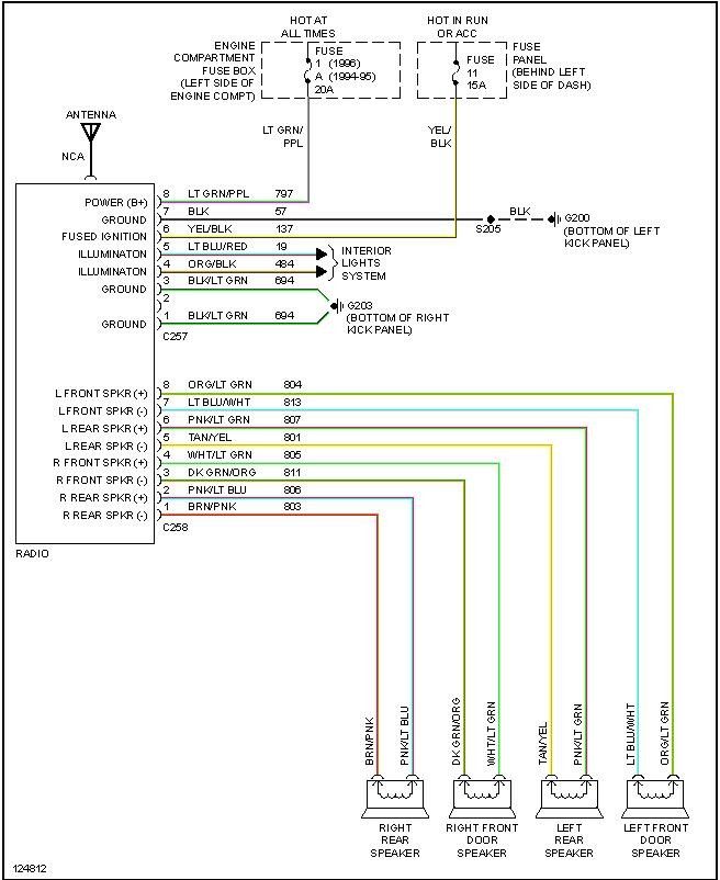
Color Coding Reference Table
The table below summarizes the common wiring functions and their typical color codes for the 2001 F-150 radio harness:
| Function | Wire Color |
|---|---|
| Constant 12V | Yellow |
| Switched 12V | Red |
| Ground | Black |
| Illumination | Orange or Orange/White |
| Antenna Trigger | Blue |
| Amplifier Turn-On | Blue/White |
| Front Left Speaker (+) | White |
| Front Left Speaker (-) | White/Black |
| Front Right Speaker (+) | Gray |
| Front Right Speaker (-) | Gray/Black |
| Rear Left Speaker (+) | Green |
| Rear Left Speaker (-) | Green/Black |
| Rear Right Speaker (+) | Purple |
| Rear Right Speaker (-) | Purple/Black |
Important Access/Installation Notes
- Disconnect Battery: Always disconnect the negative battery terminal before working on wiring to prevent shorts or electrical damage.
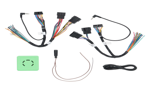
- Use a Wiring Harness Adapter: Purchase a vehicle-specific wiring harness adapter (e.g., Metra 70-5517 or equivalent confirmed for 2001 F-150). This plugs into the factory radio connector, providing labeled wires for easy connection to an aftermarket radio. This avoids cutting factory wires.
- Identify Factory Amplifier: Determine if your specific truck has the factory external amplifier (common in premium sound systems). The Blue/White wire controls this. If installing an aftermarket radio and retaining the factory amp, this wire connection is crucial.
- Antenna Type Identify if you have a fixed mast or power antenna, as the trigger wire connects differently.
Note: While online enthusiast forums and general auto repair sites (such as those referenced in the context) can offer community guidance, their diagrams might lack official verification. Cross-reference any forum-found diagrams cautiously with reliable sources or harness adapter labels.