Common Issues in 4l60e Transmission Wiring
The 4l60e transmission is prone to wiring faults that cause harsh shifts, failure to engage, or check engine lights. Key problems stem from poor connections and sensor failures. Addressing these requires referencing the wiring diagram accurately.
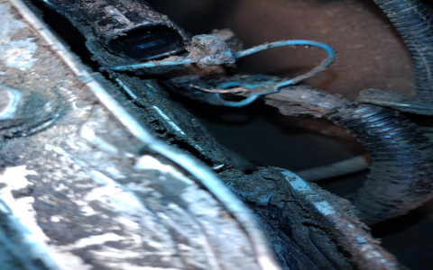
- Loose or Corroded Connectors: Often at the Transmission Control Module (TCM) or sensors like Input Speed Sensor (ISS). Fix by inspecting for damage and securing with dielectric grease.
- Damaged Wiring Harness: Exposure to heat or debris leads to frayed wires, affecting signals. Repair involves continuity tests using a multimeter and splicing with heat-shrink tubing.
- Faulty Speed Sensors: ISS or Output Speed Sensor (OSS) failures trigger limp mode. Replace after verifying voltages (typically 5V reference signal) against diagram values.
- Incorrect Wiring Modifications: Aftermarket upgrades often misroute wires, causing communication errors. Revert to factory wiring layouts per diagram specifications.
Understanding the 4l60e Wiring Diagram
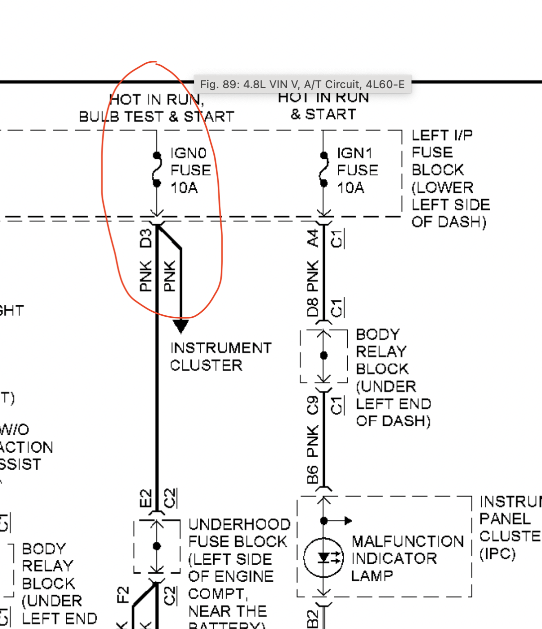
The diagram outlines critical paths: Power sources (red for +12V), grounds (black or brown), and sensor circuits (e.g., ISS uses tan/black wires). Focus on TCM pins for diagnostic scans:
- Pin 1 (Ignition Power) must show battery voltage to ensure TCM activation.
- Pins 8-10 handle ISS/OSS signals; discrepancies indicate shorts or open circuits.
- Shift solenoid circuits (e.g., SOL-A, SOL-B) use color-coded lines—check for continuity to avoid pressure faults.
Always cross-verify with your vehicle’s specific diagram to resolve issues effectively.