
Accurate diagnosis of 3-wire camshaft position sensor (CMP) circuits is essential for resolving related engine problems like no-starts, misfires, poor running, or check engine lights (P0340-P0349). Understanding the wiring harness and systematic testing is key.
Core Function & Harness Pinout
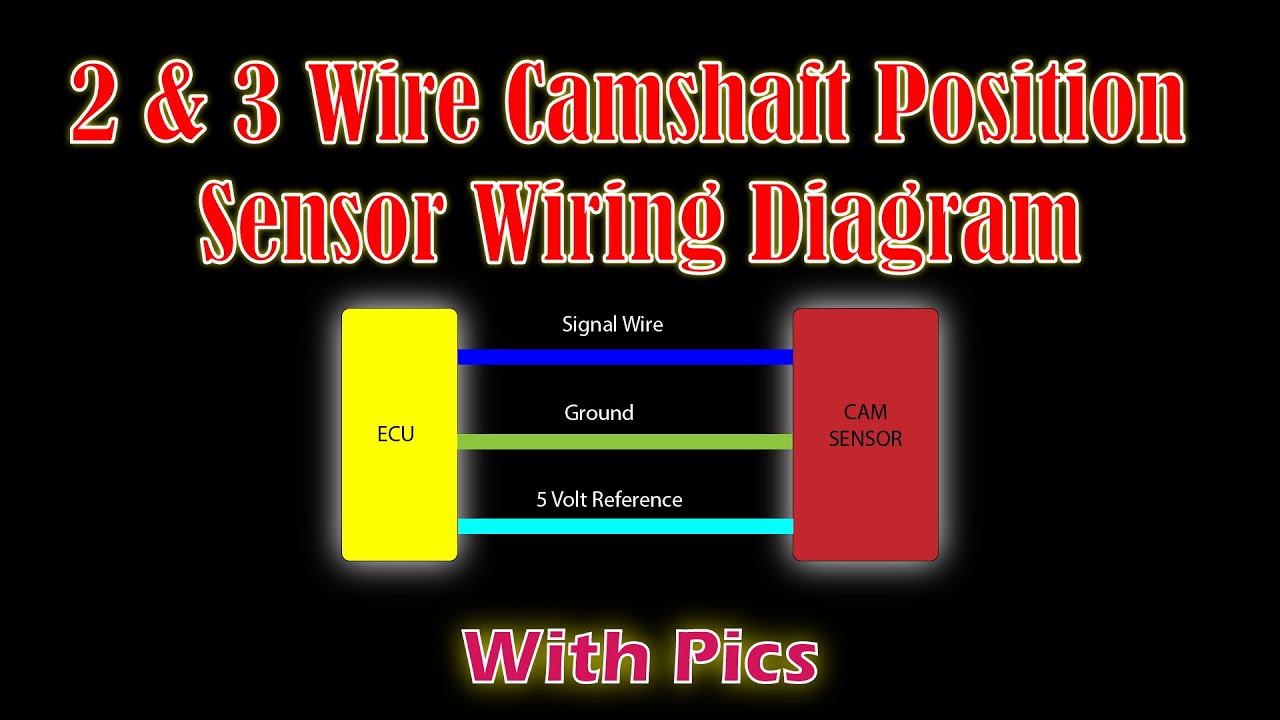
The Hall-effect type CMP sensor requires three wires for operation:
- Power Supply (Reference Voltage): Typically 5V or 12V, supplied by the Powertrain Control Module (PCM). Labeled as REF V, VCC, or +B. Wire color varies widely (common: Red, Violet, Grey, Orange - ALWAYS verify).
- Ground: Sensor return path to the PCM or engine ground. Labeled GND, SIG RTN. Wire color often Black, Black/White, or Brown.
- Signal Output: Outputs a digital square wave signal (high/low voltage pulses) corresponding to camshaft position. Labeled SIG, OUT, or CPK. Wire color varies (common: Green, Blue, Yellow, White - ALWAYS verify).
Critical: Rely on vehicle-specific wiring diagrams for exact wire colors, connector views, and PCM pin numbers. Do not assume colors.
Diagnostic Procedures Using the Diagram
1. Visual & Physical Inspection
- Inspect the harness connector and sensor connector for damage, corrosion, bent pins, or loose connections at both ends.
- Trace the harness visually (as far as possible) for chafing, burns, or rodent damage near hot manifolds or moving components.
- Confirm sensor is correctly mounted and the air gap (if adjustable or affected by debris/mounting) is correct.
2. Power Supply (REF V) Test
- Set multimeter to DC Volts.
- Disconnect the sensor connector.
- Turn ignition ON (Engine OFF).
- Probe the Power Supply terminal at the harness connector (identified via diagram).
- Good: ~5V or Battery Voltage (usually 12V) depending on system. If 0V:
- Check related PCM fuse(s).
- Check continuity from PCM REF V pin to harness connector. Repair open circuit.
- Possible PCM internal fault (less likely).
3. Ground (GND) Circuit Test
- Set multimeter to Ohms.
- Probe the Ground terminal at the harness connector.
- Connect the other probe to a known-good engine ground point (battery negative).
- Good: Low resistance (typically less than 0.5 Ohms). High resistance indicates high resistance or open circuit.
- Check for poor grounds at PCM or shared ground points using the diagram.
4. Signal Output Circuit Test (Static)
- Set multimeter to DC Volts.
- Probe the Signal Output terminal at the harness connector.
- Connect the black probe to battery negative or the verified harness ground terminal.
- Turn ignition ON (Engine OFF).
- Good: Should usually show a fixed voltage (could be low, like 0.1-0.5V, battery voltage, or near REF V). This state depends on the specific cam position relative to the sensor target.
- If low: Check for short to ground on the SIG wire.
- If high or REF V: Check for open circuit or short to power on the SIG wire (or internal sensor short).
5. Signal Output Test (Dynamic - Best Test)
- Recommended Tool: Oscilloscope. Alternatively, use a multimeter set to AC Volts or Hz/Freq if capable.
- Oscilloscope:
- Reconnect the sensor connector. Back-probe the SIG wire.
- Crank or run the engine.
- Good: Clean, square, consistent digital pulses switching between a low (~0.5V) and high (~REF V) state as the camshaft rotates. Pattern should match specifications.
- Faulty: Missing pulses, erratic pattern, amplitude drop, excessive noise, or flatline (constant high or low).
- Multimeter (ACV/Freq):
- Crank the engine.
- Good: Fluctuating AC voltage or a steady frequency reading matching camshaft RPM.
- Faulty: Zero or unstable voltage/frequency.
- Erratic/missing signal with confirmed good wiring indicates faulty sensor.
6. Short Circuit Checks
- Disconnect BOTH PCM connector and sensor connector.
- Check continuity between SIG Output terminal and Ground terminal. Should be infinite Ohms (open). Low Ohms indicates short to ground.
- Check continuity between SIG Output terminal and Power (REF V) terminal. Should be infinite Ohms. Low Ohms indicates short to power.
- Repair shorts found in the harness.
Common Failures & Confirmation
- Failed Sensor: Common cause after confirming harness integrity.
- Open Circuit: Broken wire causing missing signal.
- Short to Ground/Power: Harness damage causing SIG output to be pulled low or high.
- Poor Connection/Corrosion: Intermittent signal issues.
- Damaged Tone Ring/Reluctor: Chip or missing tooth disrupting signal.
Confirm: After repair or sensor replacement, clear codes and verify correct operation, absence of symptoms, and a clean signal pattern on a scope.