For precise diagnosis and repair of your 2003 Chevrolet Tahoe air conditioning system, understanding the core components and their interactions is essential. The R134a refrigerant cycle relies on specific parts functioning correctly.
Key A/C System Components (2003 Tahoe)
Compressor: Driven by the serpentine belt via an electromagnetic clutch. Compresses low-pressure gaseous refrigerant into high-pressure/high-temperature gas. Located front, engine lower right (driver side).
Condenser: Mounted in front of the radiator. Cools and liquefies high-pressure refrigerant gas discharged from the compressor using airflow. Contains the High-Pressure Refrigerant Pressure Switch.
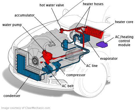
Receiver/Drier: Stores liquid refrigerant, removes moisture via desiccant, and filters debris. Located between the condenser and thermal expansion valve (TXV), usually near the radiator top or side.
Thermal Expansion Valve (TXV): Precisely meters liquid refrigerant flow into the evaporator core based on evaporator outlet temperature. Attached to the evaporator housing inlet line within the engine bay.
Evaporator Core: Situated inside the HVAC housing under the dash. Liquid refrigerant expands and evaporates here, absorbing cabin heat. Contains the Low-Pressure Refrigerant Pressure Switch and evaporator temperature sensor.
Accumulator: Not used in TXV systems (like the 2003 Tahoe). The receiver/drier fulfills the storage/filtering role.
Refrigerant Lines:
- High-Side: From compressor discharge to condenser, then receiver/drier to TXV (smaller diameter, hot).
- Low-Side: From evaporator outlet back to compressor suction (larger diameter, cold).
Essential Diagnostic Checks
- Compressor Engagement: Verify the clutch activates when A/C is set to MAX/COLD (check fuse, relay, low/high pressure switches, clutch coil).
- Refrigerant Charge: Use manifold gauges. Incorrect pressures cause poor cooling or compressor damage.
- Condenser Airflow: Ensure debris-free fins and functioning cooling fans.
- HVAC Controls & Blower: Confirm proper airflow direction and blower motor speeds.
- Pressure Switches: Test the high-pressure switch (condenser) and low-pressure switch (evaporator outlet line) for continuity.
Critical Repair Notes
- Always recover refrigerant before opening any sealed components.
- Replace the receiver/drier whenever the system is opened.
- Flush contaminated lines and replace filter screens after compressor failure.
- Lubricate O-rings with PAG oil (ND-8 specification) before installation. Do not use petroleum-based lubricants.
- Accurate evacuation (deep vacuum) is mandatory before charging to remove moisture and non-condensables.
- Charge refrigerant by weight per manufacturer specs (approx. 1.75 - 2.0 lbs for 2003 models).
Safety: Wear eye protection. High-pressure refrigerant can cause severe injury. Handle pressurized lines and components cautiously. Consult specific component location diagrams for your exact model (base or Z71) when accessing components.