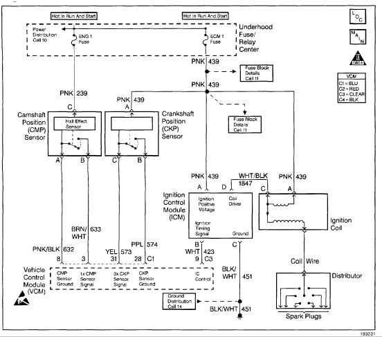
To correctly connect a 2005 Chevrolet Astro ignition wiring harness, follow this sequence precisely.
Pre-Connection Steps
Disconnect the Battery: Always disconnect the negative terminal first. Wait 15 minutes to allow airbag system capacitors to discharge.
- Gather materials: Wiring diagram specific to your Astro's engine & trim level, multimeter, wire strippers, connectors, heat shrink tubing, electrical tape.
- Identify all ignition components: Ignition switch, ignition coil, starter solenoid, distributor (if equipped), powertrain control module (PCM) connectors.
Core Wiring Connections
- Starter Circuit (Purple Wire): Connect the thick purple wire from the ignition switch directly to the "S" terminal on the starter solenoid. Route away from exhaust manifolds.
- Ignition Switch Power (Pink Wire): Connect the primary switched ignition power (typically pink) from the ignition switch to:
- Ignition coil positive terminal (+)
- Ignition control module (ICM) power input
- Fuel pump relay control
- PCM ignition feed (specified pin)
- Ignition Start Signal (Yellow Wire): Run the ignition "Start" signal wire (often yellow) to the PCM's dedicated start input pin for fuel/spark timing during cranking.
- Ignition Control Module (ICM) & PCM:
- Connect the ICM reference signal wire to the PCM's designated reference pin.
- Connect the ICM/PCM bypass control wire per the diagram.
- Ensure PCM ground wires are secured to the engine block or chassis ground point.
- Coil Connections: Connect the ICM's ignition coil control wire to the coil negative (-) terminal. Confirm coil positive (+) has switched 12V.
Critical Safety Checks
- Insulation: Secure all connections with crimp connectors and insulate with heat shrink. Prevent grounds or shorts.
- Circuit Verification: Before reconnecting battery:
- Test continuity between ignition switch terminals and component terminals in both "Off" and "Run/Start" positions.
- Verify no continuity exists between any ignition wire and chassis ground using a multimeter (Ohm setting).
- Preliminary Power Test: Temporarily connect the battery negative. With ignition in "Run" (not start), check for 12V at:
- Coil positive (+) terminal
- ICM power wire
- PCM ignition feed pin
Disconnect battery immediately after checks.

Final Testing
Secure Battery Connection: Reconnect the battery negative terminal firmly.
- Attempt start. Listen for distinct starter engagement and smooth cranking.
- If engine starts but idles roughly or stalls, verify ignition timing reference signal using a scan tool.
- Check for Diagnostic Trouble Codes (DTCs) related to ignition (e.g., P035x coil codes).
- Inspect all ignition connections for heat after 5 minutes of operation.

