Installing a headlight switch wiring harness in a Chevy truck requires basic mechanical skill and electrical knowledge. Always disconnect the negative battery terminal before starting any electrical work. Below is a concise guide, referencing a typical wiring diagram configuration.
Tools & Materials
- New OEM or compatible headlight switch
- Wire strippers/crimpers
- Electrical tape or heat shrink tubing
- Multimeter (recommended for verification)
- Basic hand tools (screwdrivers, panel removal tools)
- Repair connectors/wire (if splicing required)
Procedure
1. Disconnect Battery: Locate the negative (-) battery terminal and disconnect it completely to eliminate shock/fire risk and prevent accidental shorts.
2. Access the Switch:
- Parking Brake: Set firmly.
- Remove Dash Trim Panels: Carefully use appropriate tools to pry off trim bezels surrounding the instrument cluster and headlight switch. Specific panel locations vary by model year.
- Locate Switch: Identify the factory headlight switch assembly.
3. Remove Old Switch:
- Push Knob In & Depress Release Tab: Most Chevy switches require pushing the knob fully inward while simultaneously depressing a small tab (often on the top surface of the switch) to unlock it from the bezel.
- Pull Knob/Switch Assembly Out: Once the release tab is depressed, pull the entire knob and switch assembly outward from the dashboard.
- Unplug Wiring Harness: Locate the multi-pin connector at the rear of the switch and depress any locking tab. Carefully pull the connector straight off the switch terminals.
4. Identify Wires (Diagram Reference): Consult your specific year/model Chevy truck wiring diagram. Match wire colors/terminal markings on the harness connector to the diagram. Common functions include:
- Battery Power Supply: Typically Orange (constant 12V+, often fused).
- Headlight Power Output (Low Beam): Often Tan wire.
- Headlight Power Output (High Beam): Often Light Green.
- Parking Light Output: Often Brown or Dark Brown.
- Dimmer Rheostat (Dash Lights): Often Gray or similar (variable power).
- Instrument Illumination Feed: Often Gray/Yellow.
- Ground: Typically Black (essential).
- Dome Light/Delay Feed: Often Purple/Yellow (used for door-activated interior lights/delay).
Critical: Verify wire functions using your truck's diagram as color codes can differ.
5. Install New Switch:
- Plug in Connector: Ensure connector pins align correctly and push the harness connector firmly onto the terminals of the new headlight switch until it clicks/locks securely.
- Test Functions (Optional but Recommended): Temporarily reconnect the negative battery cable. Without installing the switch into the dash, turn the knob/dimmer to verify:
- Parking lights activate
- Headlights (Low & High beam) function
- Dome light delay works (if applicable)
- Dash illumination dims/brightens
Disconnect battery negative immediately after testing.
- Position Switch: Carefully position the new switch assembly into the dash opening.
- Lock Switch: Push the knob fully inward to engage the locking mechanism (usually the same release tab used for removal snaps back into place). The switch should be firmly seated.
6. Reassemble:
- Replace all trim panels and bezels securely.
- Reconnect Battery: Attach the negative battery terminal last.
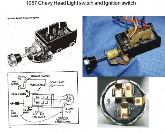
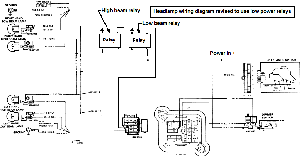
Basic Wiring Concept Diagram
Understanding the core connections aids troubleshooting:
- Power In: Constant 12V+ (e.g., Orange wire) feeds the switch.
- Power Out: Switch routes power to:
- Parking Lights (Brown)
- Low Beams (Tan)
- High Beams (Light Green - usually via separate relay control)
- Ground: Black wire to chassis ground completes all circuits.
- Dash Dimming: Gray wire provides variable power to illumination lights.
- Dome Feed: Purple/Yellow wire connects to interior light circuit.
Key Tips:
- Diagram is Essential: Never rely on memory; use the specific diagram for your truck.
- Secure Connections: Ensure terminals are clean and connectors seat fully. Loose connections cause flickering or failure.
- Protect Wiring: Avoid routing wires near sharp edges or moving parts; use existing grommets through the firewall.
- Replace Damaged Plugs: If the connector is brittle/broken, replace the pigtail.
If wiring is significantly damaged or modified, consult a professional.