Creating a motorcycle mirror wiring diagram requires understanding your bike’s electrical system and planning connections clearly. Follow these steps for a functional DIY setup.
Required Tools and Materials
- Multimeter for voltage testing
- Wire strippers and crimping tool
- Heat-shrink tubing or electrical tape
- Soldering iron and solder (optional for secure connections)
- Circuit tester or test light
- Zipties and wire loom for organization
Step-by-Step Diagram Creation
1. Identify Power Sources: Locate switched ignition power (activates with key) and ground points using a multimeter. Common sources include accessory fuse taps or spare connectors near the handlebars. Avoid direct battery connections to prevent drain.
2. Map Mirror Functions: Determine if mirrors have turn signals, heating, or adjustment motors. Note wire colors and functions using manufacturer documentation or continuity testing.
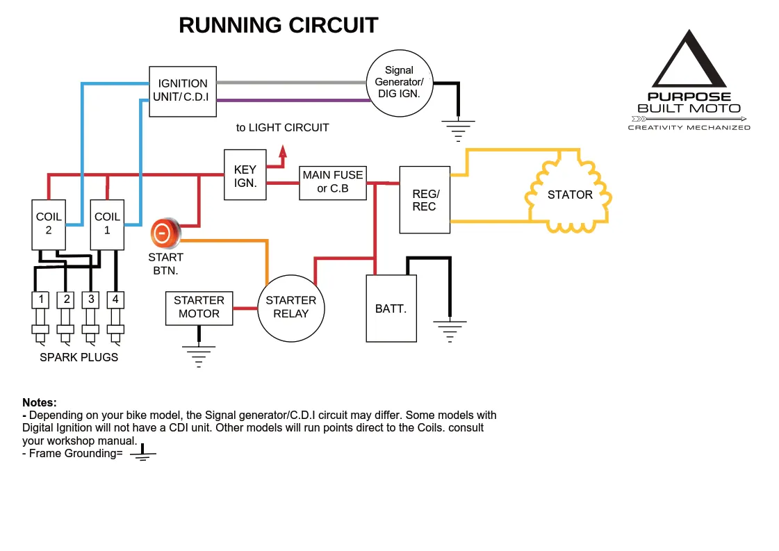
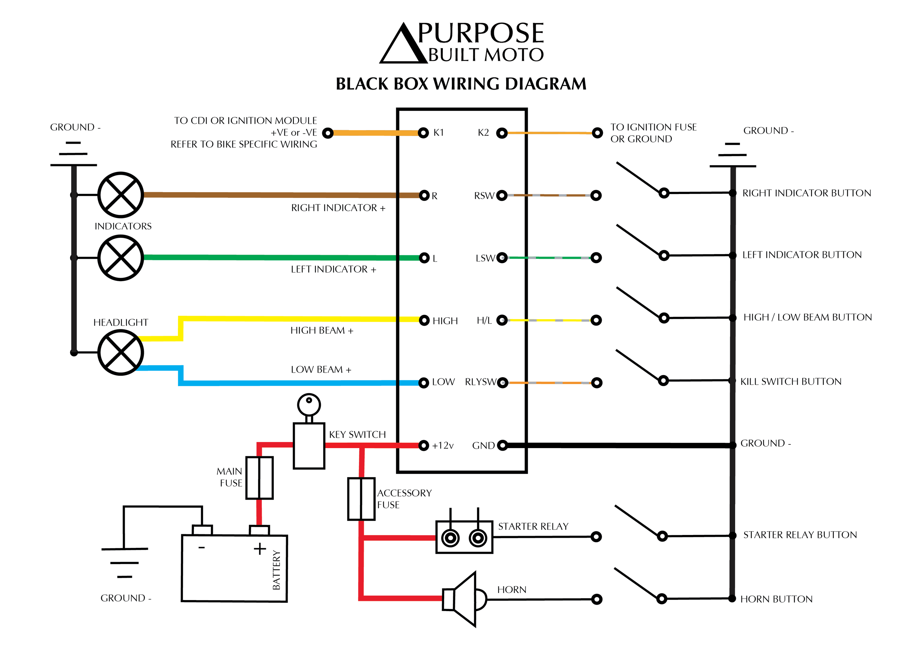
3. Sketch the Circuit: Draw a schematic with:
- Power source (labeled with voltage, e.g., 12V)
- Fuse (3-5A recommended)
- Switch or relay for heated mirrors (if applicable)
- Ground symbol for all ground connections
- Wire paths between components
Use standard symbols and label wire colors.
4. Calculate Wire Gauge: Use 18-22 AWG wire for low-current mirrors. For heated mirrors or high-power LEDs, choose 14-16 AWG to handle load. Cross-reference ampacity charts.
5. Plan Routing: Trace paths from mirrors to power/ground avoiding moving parts, heat sources, and sharp edges. Designate a common grounding point near the frame.
Safety and Installation Tips
- Disconnect the battery before wiring.
- Solder and seal connections with heat-shrink tubing for waterproofing.
- Test circuits with a multimeter before permanent mounting.
- Secure wires every 6 inches with zipties to prevent vibration damage.
Troubleshooting
No Power: Verify fuse integrity and ground continuity. Check for corroded terminals.
Intermittent Operation: Inspect for pinched wires or loose connectors. Reflow solder joints if needed.
Signal Malfunction: Ensure turn signal wires don’t share circuits with incompatible components.