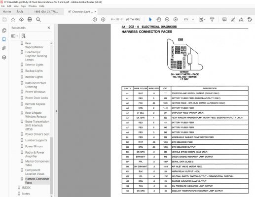
Mastering GMT400 firewall connector diagnostics requires understanding their dual-connector system, typically C100 (smaller, often near brake booster) and C200 (larger, center). Here’s the pro approach:
Essential Preparation
Tools Required:
- Factory Service Manual electrical section for your specific year and model
- Digital Multimeter (DMM)
- Test light
- Terminal depinning tool kit
- Quality terminal probe kit
- Safety glasses
Critical First Step:
- Disconnect the negative battery terminal before probing connectors to prevent short circuits.
Pinout Identification Process
1. Connector Physical Identification & Orientation:
- Identify C100 and C100 locations reliably using manual diagrams, not assumptions.
- Note connector halves: Front (engine bay side) mates with Rear (cab side). Pin numbering is relative to each half.
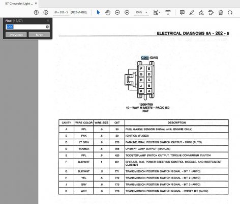
2. Pin Numbering Decoding:
- Locate tiny molded numbers/letters or arrows indicating Pin 1 position on connector housing.
- Rows usually marked alphabetically top-to-bottom (e.g., row A, B, C).
- Columns marked numerically left-to-right from Pin 1.
- Pro Tip: If markings are damaged, always reference the mating connector's pinout and trace continuity.
3. Service Manual Pinout Interpretation:
- The manual lists each circuit by Pin Number (e.g., C100-Front, Pin C7), Wire Color, Circuit Function (e.g., "IGN 1 Feed to ECM").
- Verify Wire Color: Faded or repainted wires require probing confirmation.
- Circuit Functions Vary: Never assume; check exact model/year. PCM/ECM inputs, grounds, fused feeds share connectors.
4. Pro Probing Techniques:
- Backprobing: Insert probe tip gently into connector rear through the weather seal using terminal-specific probes.
- Disconnect & Probing: Remove connector halves, probe terminals using the proper pin guide.
- Test Logic:
- For Grounds: Confirm continuity between pin and chassis ground.
- For Powers/Feeds: Verify voltage present under load with test light/DMM after reconnecting battery/connectors.
5. Troubleshooting Specifics:
- Bad Grounds: Check multiple grounds simultaneously. Suspect corroded pins if voltage drops under load. Voltage reference checks are critical for sensors.
- Open Circuits: Probe pin-to-pin continuity through the firewall between connector halves.
- Short Circuits: Perform isolation resistance tests to power and ground.
Pro Technician Tips:
- Corrosion First: Most issues stem from corroded terminals. Remove pins, clean contacts with electrical cleaner.
- Inspect Terminal Tension: Use terminal test pins to ensure secure mating. Replace loose terminals using proper GM-Spec pins and tools.
- Year Matters: OBD-I (94-95) and OBD-II (96+) have significant ECM/PCM pinout differences.
- Manual Supplement: Cross-reference ground splice pack locations noted in the manual for thorough diagnosis.