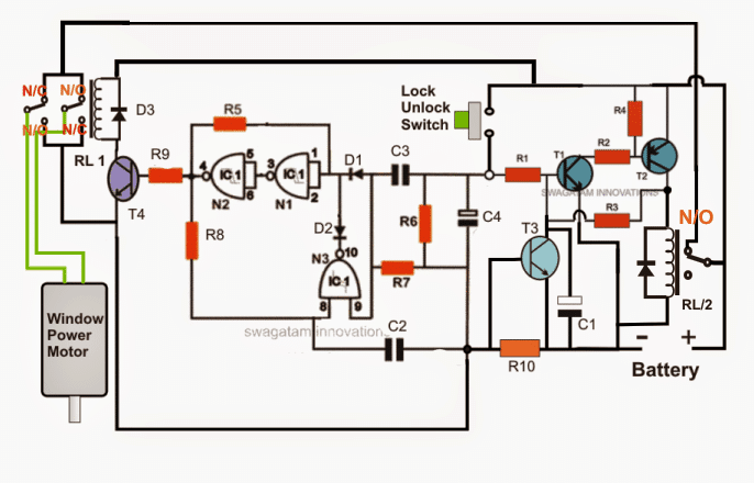
Understanding power window switch wiring requires familiarity with basic automotive circuits. This guide outlines common configurations and essential safety steps for DIY diagnostics or repairs.
Safety Precautions First
- Disconnect Battery: Always disconnect the vehicle's negative battery terminal before starting.
- Use Wiring Diagrams: Obtain the specific schematic for your vehicle's make, model, and year. Generic guides may differ.
- Test Components: Verify switch functionality and motor operation before extensive wiring checks.
Core Power Window Circuit Components
- Master Switch (Driver's Door): Controls all windows, often includes lockout function.
- Passenger Door Switches: Local control for each window (receives signals via the driver's master switch).
- Window Motors: 12V DC reversible motors in each door.
- Wiring Harness: Connects switches, motors, power sources, and grounds through the vehicle body/door jambs.
- Relay/Fuse/Circuit Breaker: Provides protected battery power.
Typical Wiring Schematic Principles
1. Power Distribution:
- A constant Battery feed (usually fused, often 20-30A) connects to the master switch module.
- This power feeds the master switch and is distributed downstream to the individual window circuits.
2. Master Switch Operation:

- Each window circuit within the master switch has five terminals common to the motor:
- Battery+ Input (Common Feed)
- Output to Motor Terminal A (Up)
- Output to Motor Terminal B (Down)
- Ground (through the switch logic)
- Often a Lock/Enable signal output to passenger switches
- Pressing UP connects the Battery+ feed to the motor's "Up" terminal and grounds the motor's "Down" terminal.
- Pressing DOWN reverses polarity, connecting Battery+ to the motor's "Down" terminal and grounding the "Up" terminal.
3. Passenger Switch Operation:
- Requires both power and ground signals from the master switch module to function.
- The master switch sends switched power and ground (often a combined "Enable" signal) to the passenger switch when not locked out.
- Passenger switches then operate similarly to the master switch, reversing polarity to their local motor.
4. Window Motor:
- A reversible 12V DC motor with two main terminals (Motor Terminal A and Motor Terminal B).
- Reversing the positive and negative connections across these terminals changes the motor's direction (up/down).
Key Wire Colors (Common Conventions - VERIFY WITH YOUR DIAGRAM!)
| Function | Driver Switch (Common Colors) | Passenger Switch (Common Colors) |
|---|---|---|
| Constant Battery Feed | Red, Orange, Yellow, White | Received via Harness |
| Ground | Black, Brown | Received via Harness |
| Motor Terminal A (e.g., Up) | Green, Light Blue, Blue/White | Blue, Green/White |
| Motor Terminal B (e.g., Down) | Blue, Dark Blue, Blue/Black | Green, Blue/Red |
| Passenger Switch Enable/Lock | Yellow/Black, Tan, Gray | Yellow/Black, Tan, Gray |
Troubleshooting Basics
- No Power Anywhere: Check main fuse/breaker and battery connection to master switch.
- One Window Not Working:
- Check fuse specific to that circuit (if separate).
- Swap master switch segment with a known good one.
- Test continuity between master switch output wires and motor terminals.
- Apply 12V directly to motor terminals to verify motor function and wiring.
- Passenger Window Only Works from Master Switch: Likely passenger switch failure, lack of "Enable" signal from master, or wiring break to the passenger switch.
- Motor Runs But Window Stuck: Mechanical failure (regulator, track) not electrical.
DIY Tips
- Multimeter Essential: Test for presence of Battery+ voltage at key points (master input) and voltage drop/continuity along suspected paths.
- Focus on Grounds: Poor ground connections are common failure points. Verify all switch and motor grounds.
- Door Jamb Harness: Frequent location for broken wires due to constant flexing. Inspect visually and test wires for breaks.
- Switch Pin Diagrams: Refer to the schematic for terminal identification on the switch connector itself.
- Ivy Method: Trace from power source (battery -> fuse -> switch) to motor, then to ground. Verify each segment.
