
Fundamental PATS Operating Principle
Ford's Passive Anti-Theft System (PATS) immobilizes the engine unless it receives the correct encrypted signal from a programmed ignition key via the transceiver antenna ring surrounding the ignition cylinder. An incompatible signal triggers immobilization by disrupting starter engagement and fuel delivery.
Common Scenarios Requiring PATS Bypass
- Loss or damage to all programmed ignition keys.
- Malfunctioning PATS transceiver or antenna.
- Engine swaps involving non-PATS modules without PATS module retention.
Caution: Bypassing factory security systems often violates vehicle certification regulations.
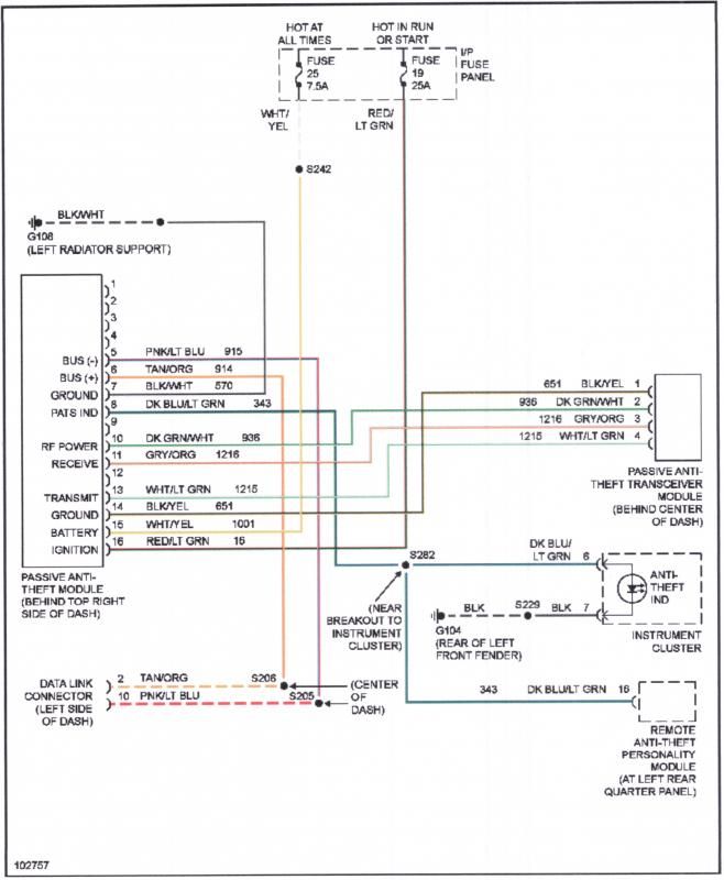
Critical Bypass Module Wiring Connections
An aftermarket bypass module interfaces with PATS components. Key circuits include:
- Constant +12V & Ground: Module primary power (typically RED & BLACK wires). Must connect directly to battery/constant power source and chassis ground.
- Ignition Switched +12V (ACC): Triggers module logic (often WHITE wire). Connect to fuse box accessory circuit.
- Transponder Antenna Ring Interface: Module connects in-line between the transceiver antenna ring and PCM using specific wires (e.g., BROWN/WHITE & BROWN/BLACK). This emulates key presence.
- Starter Interrupt Bypass: Module cuts the starter disable circuit between PCM and starter relay control (typically involves severing the original Light Green/Yellow wire). One end connects to bypass module output.
- Fuel Enable Bypass: Module overrides the PATS fuel disable signal (often involves the Dark Green/Purple fuel pump control wire). Severing and patching through the module is required.
Essential Implementation Tips
- Confirm Pinouts: Verify year/make/model wiring diagrams for precise PCM connector terminal identification (pin location and wire color). Colors vary significantly.
- Secure Power & Ground: Poor connections cause system failure. Solder and heat shrink splices.
- Module Placement: Mount securely away from heat sources and moving parts near ignition lock cylinder/PCM.
- Meticulous Wire Identification: Misidentification causes damage. Use multimeter for continuity testing against factory diagrams.
- Insulation is Critical: Properly insulate every splice and connection point with heat shrink tubing to prevent shorts.
- Diesel Specifics: PATS on diesel Ford vehicles often has additional fuel injector control circuits that must be bypassed.
Safety & Legal Disclaimer
Bypassing PATS permanently impairs the vehicle's factory theft deterrent. This modification is typically illegal for on-road vehicles in many regions and compromises security. Perform at your own discretion, understanding potential legal and safety implications.