The 3 Bypass Passkey 3 module facilitates the integration of aftermarket remote starters or security systems into vehicles equipped with GM Passkey III immobilizer systems. Correct wiring is critical for functionality and safety.
Core Terminal Functions
Identify these essential terminals on the bypass module:
- 1st Wire (Typically Red): Connect to constant +12V (Battery Positive). Use an appropriate fused link.
- 2nd Wire (Typically White): Connect to a solid vehicle ground (Chassis).
- 3rd Wire (Typically Gray/Brown or Data Bus): Connect to the vehicle's serial data bus line. Location varies (often OBD-II port, IPC, or BCM). Consult specific vehicle wiring diagrams.
Wiring Sequence
Follow this sequence for a typical installation:
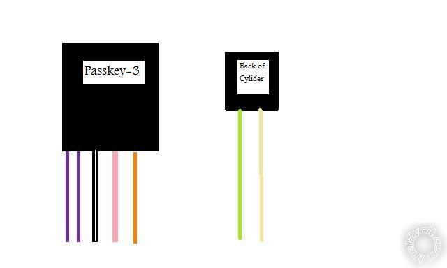
- Identify Vehicle Harness: Locate the vehicle's ignition harness and Passkey III transponder wire (usually Violet/White, Violet/Black; specific to GM models).
- Interrupt Transponder Wire: Cut the Passkey III transponder wire.
- Connect Module to Transponder Wire: Connect the module's Vehicle Side Transponder terminal to the cut wire end leading towards the vehicle's ignition cylinder/key reader. Connect the module's Immobilizer Side Transponder terminal to the cut wire end leading towards the vehicle's immobilizer module/BCM.
- Connect Module Wires: Connect the module's 1st wire (Red) to constant +12V, 2nd wire (White) to ground, and 3rd wire (Data Bus) to the vehicle's serial data line.
- Connect T-Harness (Optional/Recommended): If using a T-harness (highly recommended), plug it inline between the vehicle's ignition switch harness and the vehicle-side connector, then connect the bypass module's inputs/outputs to the corresponding T-harness wires.
Critical Considerations
- Vehicle Pinout is Paramount: Wiring colors and locations vary significantly between GM models and years. Always verify using reliable, vehicle-specific wiring diagrams.
- Data Bus Connection Accuracy: Incorrect data line connection is a common failure point. Double-check the required connection point.
- Learning Procedure: After wiring, the module often requires a specific learning sequence using the master key(s) to program the bypass. Follow the module manufacturer's instructions precisely.
- Disconnect Battery Negative: Always disconnect the vehicle's negative battery terminal before beginning any wiring work to prevent short circuits or module damage.
- Secure Connections: Use proper crimp connectors, solder and heat shrink, or high-quality taps. Prevent shorts or loose connections.
Thoroughly researching the specific vehicle's wiring details is non-negotiable for a successful and secure installation of the Passkey 3 bypass module.