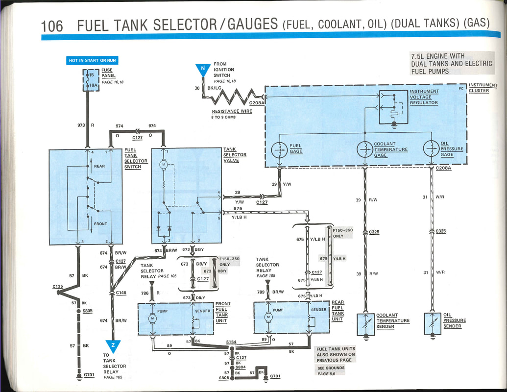
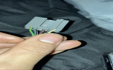
Accurately identifying fuel pump wiring colors is critical for diagnosis, testing, or repair on Ford vehicles. Wiring colors often vary by model year and specific powertrain. This guide covers common standards, but ALWAYS verify with a vehicle-specific wiring diagram.
The Ford Fuel Pump Circuit Basics
The circuit typically includes:
- Power Source: Fuel Pump Relay output (Switched Battery Positive).
- Control: Powertrain Control Module (PCM) energizes the Fuel Pump Relay.
- Safety: Inertia Fuel Shutoff (IFS) Switch (often in passenger footwell or trunk).
- Load: The Fuel Pump assembly itself.
- Ground: Dedicated chassis or body ground.
- Fuel Tank Pressure Sensor Wiring (if equipped).
Common Ford Fuel Pump Wiring Color Codes
Disclaimer: Colors can and do differ. These represent frequent patterns:

- Fuel Pump Power Feed (To Pump from Relay/IFS): Frequently Orange/Light Blue Stripe (O/LB) or Violet/Orange Stripe (V/O). Often the thickest wire at the pump connector.
- Fuel Pump Ground (Return Path): Very commonly Black/Light Green Stripe (BK/LG) or Black/Pink Stripe (BK/PK).
- Inertia Fuel Shutoff (IFS) Switch Feed: The wire coming from the relay TO the IFS is often Pink/Black Stripe (PK/BK).
- Inertia Fuel Shutoff (IFS) Switch Output: The wire going FROM the IFS to the pump is commonly the same color as the main pump feed above (e.g., O/LB).
- Fuel Pump Relay Coil Control (from PCM): Often Light Green/Yellow Stripe (LG/Y) or Dark Green/Orange Stripe (DG/O). Powers the relay coil.
- Fuel Tank Pressure (FTP) Sensor Wiring: Requires 3 wires:
- Reference Voltage (5V): Often Light Blue/Red Stripe (LB/R) or Violet/White Stripe (V/W).
- Signal Return: Often Grey/Red Stripe (GY/R).
- Ground: Often Black/Pink Stripe (BK/PK) or similar.
- Fuel Pump Driver Module (FPDM) Control (Late Models with PWM): May use Light Blue/Orange Stripe (LB/O) for PWM signal and distinct power/grounds. Complex systems require specific diagrams.
Essential Safety & Verification Steps
- DISCONNECT BATTERY: Before servicing any wiring.
- CONFIRM WITH A DIAGRAM: Colors can change. Obtain the specific wiring diagram for your exact Ford vehicle (model year, engine).
- USE A DIGITAL MULTIMETER (DMM):
- Verify Battery Voltage (≈12V+) on the feed wire for 1-2 seconds after turning the key ON (engine OFF).
- Confirm Good Ground (continuity to chassis) on the ground wire with battery disconnected.
- Check continuity through the Inertia Switch if a "no power to pump" issue exists. Reset it by pressing the button.
- FIRE RISK: Fuel vapors are dangerous. Never probe wires near leaking fuel or sparks.
Identifying Wires at the Pump Assembly (Common Connector)
- Two-Wire Pump: Power Feed (Thick - O/LB, V/O) + Ground (BK/LG, BK/PK).
- Three-Wire Pump Assembly: Power + Ground + Fuel Gauge Sender Signal (often Y/Bk, W/PK etc.). Sender wires are thinner.
- Four+ Wire Connector: Likely includes Fuel Tank Pressure Sensor and/or fuel level sender wires.
Always trace the thickest wires first for pump power and ground. Diagram verification is non-negotiable for accurate repair.

