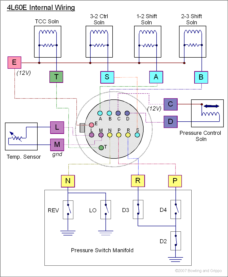
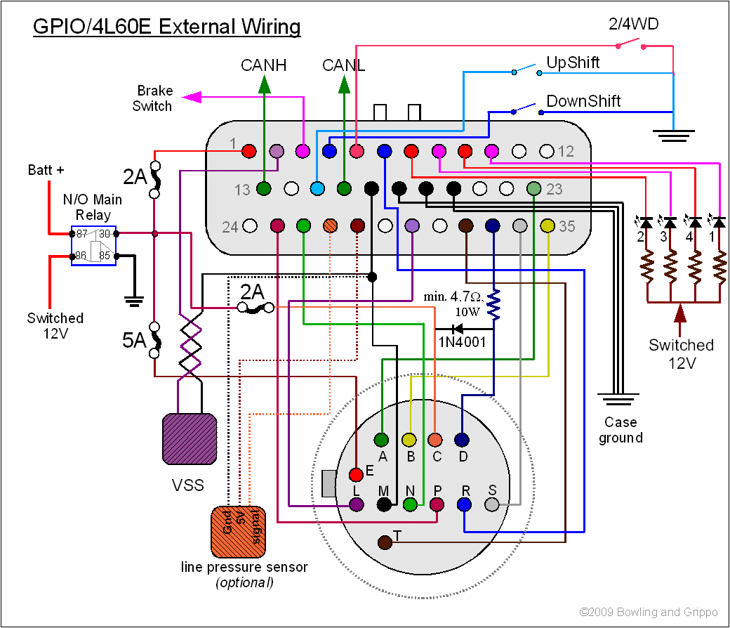
The 4L60E wire diagram outlines electrical connections for General Motors' 4L60E automatic transmission, used extensively in trucks and SUVs. Understanding it ensures proper diagnostics, repairs, or swaps.
Core Components in the Diagram
Transmission Connector (13-pin): Central interface linking internal components to the vehicle's PCM. Key terminals include:
- Pin A (Purple/White): Output Speed Sensor (OSS) signal
- Pin B (Yellow): Shift Solenoid A control
- Pin E (Dark Blue): Shift Solenoid B control
- Pin F (Red/Black): Torque Converter Clutch Solenoid control
- Pin D (Tan/Black): Pressure Control Solenoid control
- Pin M (Gray): Input Speed Sensor (ISS) signal
- Pin L (Pink/Black): +12V power supply
Sensor/Solenoid Functions
Speed Sensors: ISS monitors turbine shaft rotation; OSS tracks output shaft RPM. Mismatched signals trigger diagnostic trouble codes.

Shift Solenoids A & B: Activate clutch packs to execute gear changes via PCM pulse-width modulation.
Pressure Control Solenoid (PCS): Regulates line pressure dynamically based on throttle position and load.
TCC Solenoid: Engages torque converter lockup clutch to reduce slippage during cruising.
Critical Grounding & Power
Pin L (Pink/Black): Receives fused ignition-switched power from PCM.
Pin G (Black/White): Chassis ground; poor grounding causes erratic shifting or sensor failures.

Pin K (Black): Dedicated ground for solenoids.
Troubleshooting Notes
- Always verify wire colors against vehicle-specific diagrams (year/model variations exist).
- Resistance checks: Solenoids typically measure 20-30Ω; sensors 800-1,400Ω.
- Continuity-test circuits for opens/shorts before replacing components.
Wiring errors may cause limp mode (defaulting to 2nd gear), harsh shifts, or loss of TCC engagement.

