A vapor canister purge valve (often called a purge solenoid) is an essential component of a vehicle's Evaporative Emission Control System (EVAP). Its primary function is to control the flow of fuel vapors trapped in the charcoal canister to the engine intake manifold for combustion.
Understanding the Diagram Components
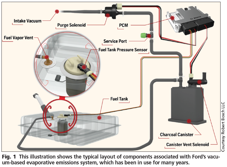
A typical purge valve diagram illustrates the key elements and their interconnections:
- Fuel Tank: Source of fuel vapors.
- Charcoal Canister: Absorbs and stores fuel vapors from the tank.
- Purge Valve (Solenoid): Electrically operated valve controlling vapor flow.
- Engine Intake Manifold: Destination for vapors under controlled conditions.
- Vacuum Lines/Hoses: Pathways connecting the components.
- Vent Valve/Solenoid: Controls fresh air intake to the canister.
- ECM/PCM: Engine Control Module that operates the purge valve based on sensor inputs.
How the System Works
The diagram visually demonstrates the operational sequence:
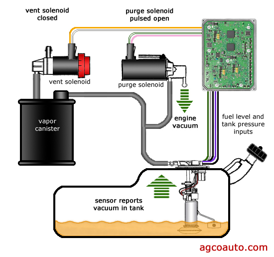
Step 1: Vapor Storage
- Vapors from the fuel tank flow into the charcoal canister.
- The purge valve remains closed (de-energized by ECM) during engine start-up and warm-up.
Step 2: Purge Activation
- Once engine reaches operating temperature and specific conditions are met, the ECM energizes the purge valve solenoid.
- The valve opens, connecting the canister to intake manifold vacuum.
Step 3: Vapor Flow
- Intake vacuum draws fresh air through the vent valve into the canister.
- This fresh air flow strips stored fuel vapors from the charcoal.
- The air-fuel vapor mixture is pulled through the open purge valve and into the intake manifold.
- Vapors mix with incoming air and are burned during normal combustion.
Step 4: System Closure
- When purge conditions end (e.g., idle, deceleration), the ECM de-energizes the solenoid.
- The purge valve spring closes the valve, stopping vapor flow.
Diagram Interpretation Tips
- Solid lines typically represent vapor or vacuum hose connections.
- The purge valve symbol usually shows a solenoid coil and a valve gate/diaphragm.
- Arrows indicate direction of vapor or air flow.
- Electrical connectors to the ECM/PCM signify control wiring.
Understanding this diagram aids in diagnosing purge valve failures—common symptoms include rough idle, difficulty starting, illumination of the Check Engine Light (often P0441, P0446, or P0455 codes), and failed emissions tests. Key test procedures involve checking solenoid operation, circuit integrity, vacuum flow, and for leaks in the associated hoses shown on the diagram.