Locating precise GM instrument cluster wiring diagrams requires authoritative, vehicle-specific sources. Verify your VIN and model year before searching.
Official GM Technical Sources
GM Service Information (S.I.) via ACDelco TDS or Dealer Access: This is the definitive OEM resource. Access requires a paid subscription but provides VIN-filtered schematics, component locations, and connector pinouts directly from GM engineering data. Diagrams include wire colors, circuit numbers, splice locations, and ground points. Essential for late-model vehicles with model-year-specific variations.
Factory Service Manuals (FSM/WSM): Hardcopy or digital versions published by Helm Incorporated for specific model years. These contain dedicated wiring diagram sections, often including detailed cluster connector views. Purchase physical copies directly from publishers or search reputable online marketplaces using your exact model year and nameplate.
Reputable Third-Party Resources
Professional-Grade Repair Databases: Services like ALLDATA or Mitchell 1 (through licensed shops or consumer versions like ALLDATAdiy) provide accurate, sourced diagrams. Search requires precise vehicle identification details (year, make, model, engine). Coverage is comprehensive but subscription-based.
Vehicle & Community-Specific Considerations
Model-Specific Forums & Enthusiast Sites: Dedicated communities for platforms (e.g., GMT800 trucks, LS-based vehicles, specific car models) often have verified diagrams uploaded by knowledgeable members. Critical: Cross-reference information using circuit numbers and wire colors against known reliable sources or factory documentation. User-contributed content may contain errors.
Technical Service Bulletins (TSBs): Occasionally, GM TSBs related to instrument cluster issues include connector views or schematic excerpts. Access these via ACDelco TDS or reputable third-party databases.
Essential Verification Steps
- Always obtain the specific diagram for your model year and trim level. Wiring differs significantly between years and options.
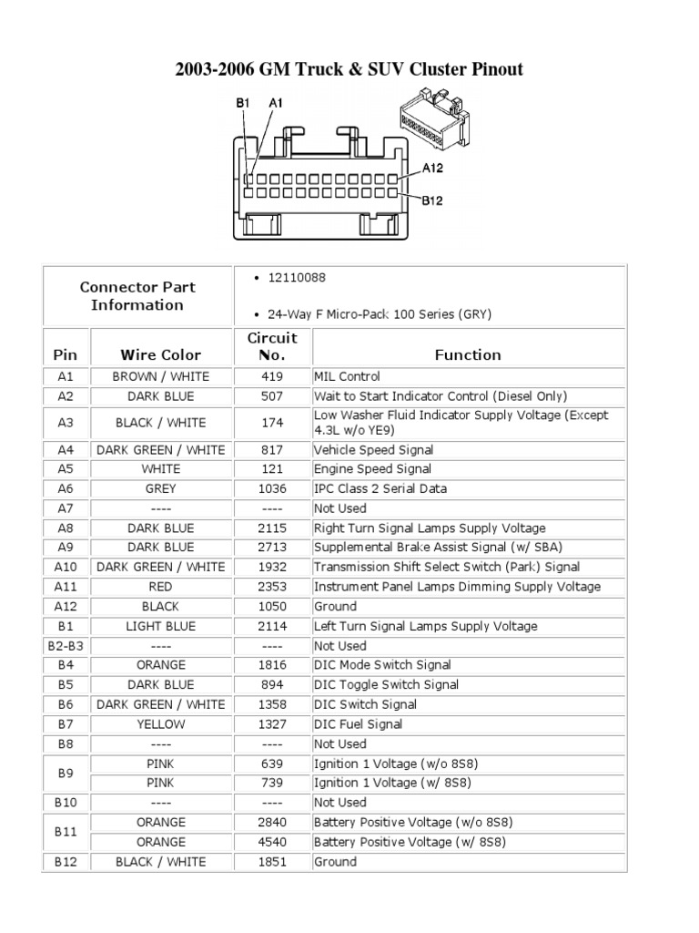
- Identify the precise connector view needed (e.g., Instrument Cluster Connector C1, IPC connector).
- Match circuit numbers and wire colors physically at the connector before making any connections or modifications.
- Use a digital multimeter to verify circuits against ground/voltage as indicated in the diagram.
Warning: Relying on unverified generic images, low-quality scans, or unconfirmed forum posts without electrical verification risks damage to modules or incorrect operation. OEM service information or professional database subscriptions offer the highest confidence.